

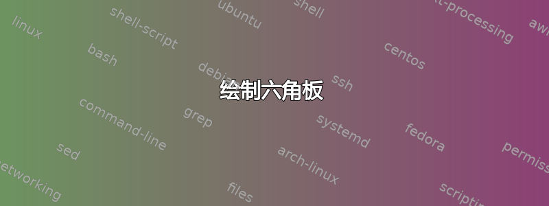
我需要画一个六边形板。我希望能够标记每个六边形并标记其大小。能够控制线条的粗细会很好,但这不是我需要的。有人能建议一种简单的方法来做到这一点吗?
这是我脑海中的图片:

编辑:Cmhughes 提出了一些使这篇文章变得更好的建议,所以就在这里!
我发现很少有资料可以帮助我解决这个问题。然而,我发现这在 stackexchange 论坛上。我尝试修改代码(从第一个答案开始)以满足我的需求(如图所示),但每次我更改某些内容时,图表都会出现一些非常奇怪的情况,例如在看似随机的方向上创建一大排六边形。
那么,我的问题是,我不知道如何修改代码以使其成为十六进制板,而不是十六进制地图。
这是我指的代码:
\documentclass{article}
\usepackage{tikz}
\usetikzlibrary{shapes}

\begin{document}
  \begin{tikzpicture}[
    hexa/.style={
      shape=regular polygon,
      regular polygon sides=6,
      minimum size=1cm,
      draw,
      inner sep=0,
      anchor=south,
      fill=lightgray!85!blue,
      rotate=30
    }
  ]
    \foreach \j in {0,...,5}{%
      \pgfmathsetmacro\end{5+\j}
      \foreach \i in {0,...,\end}{%
        \node[hexa] (h\i;\j) at ({(\i-\j/2)*sin(60)},{\j*0.75}) {};
      }
    }
    \foreach \j in {0,...,4}{%
      \pgfmathsetmacro\end{9-\j}
      \foreach \i in {0,...,\end}{%
        \pgfmathtruncatemacro\k{\j+6}
        \node[hexa] (h\i;\k) at ({(\i+\j/2-2)*sin(60)},{4.5+\j*0.75}) {};
      }
    }
    \foreach \k in {0,...,10} {%
      \node[circle,red,minimum size=1cm] at (h3;\k) {3;\k};
    }
    \foreach \k in {0,...,10} {%
      \node[circle,blue,minimum size=1cm] at (h1;\k) {1;\k};
    }
  \end{tikzpicture}
\end{document}
有人能指点一下如何修改代码吗?
此外,是否有人知道如何标记侧面,就像图中所示的那样,以及如何创建六边形的随机标记(尽管这可能只需要大量的复制和粘贴)?
答案1

这MWE使用模块(附件)中的Asymptote功能。板子 是使用单元格宽度的命令创建的,标记是在字符串数组中准备的;struct hexboardhexboard.asyhbhexboard hb=hexboard(11,xo);11string[] xo
单元节点和方向如下(方向以目的地节点命名):

粗线由起始单元格、可选前缀和后缀(如果线超出网格)、起始节点编号和方向序列构成。例如,命令
hb.oline((-10,0), prefix=(0,-1),3,4,5,0);
3使用底部单元格的节点(-10,0)作为起点,在其前面添加来自下方点的线(0,-1)
,并继续方向4、5和0(4总共段)。
最左边单元格的位置为(0,0),最右边单元格的(n-1,0)
顶部为(0,n-1),底部为(0,-(n-1))。
%
% hexboard.tex :
%
\begin{filecontents*}{hexboard.asy}
struct hexboard{
  int n;
  string[] xo;
  string xmark,omark;
  real dx,dy;

  pen gridPen;
  pen xCellBg;
  pen oCellBg;

  guide ghex;

  pair hexCenter(int k, int j){ // k= +/-
    return ((j+abs(k)/2)*dx,k*dy);
  }

  pair hexCorner(int k, int j, int a){
    return shift(hexCenter(k,j))*point(ghex,a%6);
  }

  void dot(int k, int j, int a, pen p=gridPen){
    dot(hexCorner(k,j,a),p,UnFill);
  }

  void dots(int k, int j, int a, int b, pen p=gridPen){
    for(int i=a;i<=b;++i){
      dot(hexCorner(k,j,i),p,UnFill);
    }
  }

  void oline(explicit pair start, explicit pair prefix=(0,0), explicit pair suffix=(0,0),
         explicit pen lpen=orange+2bp+opacity(0.8) ... int[]dirs){
    pair p=hexCorner((int)start.x,(int)start.y,dirs[0]);
    guide g=(p+prefix)--p;
    for(int i=1;i<dirs.length;++i){
      p+=dir(150+(dirs[i]%6)*60);
      g=g--p;
    }
    g=g--(p+suffix);
    draw(g,lpen);
  }

  void drawHex(int k, int j){
    pen bg=(substr(xo[n-1-k],j,1)=="x")?xCellBg:oCellBg;
    filldraw(shift((j+abs(k)/2)*dx,k*dy)*ghex,bg,gridPen);
  }

  void markCell(int k, int j, string v){
    if(v=="x")v=xmark;
    if(v=="o")v=omark;
    label(v,hexCenter(k,j));
  }

  void mark(){
    assert(xo.length==2n-1);
    bool b;
    string c;
    int k;
    for(int i=0;i<n;++i){
      assert(length(xo[i])==i+1);
      k=n-1-i;
      for(int j=0;j<i+1;++j){
        c=substr(xo[i],j,1);
        drawHex(k,j);
        markCell(k,j,c);
      }
    }
    for(int i=n;i<2n-1;++i){
      assert(length(xo[i])==2n-1-i);
      k=n-1-i;
      for(int j=0;j<2n-1-i;++j){
        c=substr(xo[i],j,1);
        drawHex(k,j);
        markCell(k,j,c);
      }
    }
  }

  void operator init(int n // board width
      ,string[] xo         // board marks
      ,string xmark="$\times$"
      ,string omark="$\circ$"
      ,pen gridPen=deepblue+0.4bp
      ,pen xCellBg=palered
      ,pen oCellBg=palegreen
    ){
    this.n=n;
    this.xo=copy(xo);
    this.xmark=xmark; this.omark=omark;
    this.xCellBg=xCellBg; this.oCellBg=oCellBg;
    this.dx=sqrt(3);
    this.dy=1+1/2;
    this.ghex=dir(90)--dir(150)--dir(210)--dir(270)--dir(330)--dir(30)--cycle;
    mark();
  }
}
\end{filecontents*}
%
\documentclass{article}
\usepackage[inline]{asymptote}
\usepackage{lmodern}
\begin{document}
\begin{figure}
\centering
\begin{asy}
size(10cm);

// === test hexboard
import hexboard;
string[] xo={
"o",
"xo",
"xxx",
"ooox",
"xxoox",
"xxoooo",
"oxxoxxo",
"xoxooxxx",
"oxooxooox",
"xooxooxooo",
"oxxxoxooxxo",
"oooxoxxoxx",
"xxxoxooxo",
"ooxooxxo",
"xxoooxo",
"ooxxxo",
"xoxoo",
"xoxx",
"oxo",
"xo",
"x",
};

hexboard hb=hexboard(11,xo);

label("$v$",hb.hexCorner(0,0,2)-(1,0),W);
label("$v^\prime$",hb.hexCorner(0,10,5)+(1,0),E);

label("$w$",hb.hexCorner(-10,0,3)-(0,1),S);
label("$w^\prime$",hb.hexCorner(10,0,0)+(0,1),N);

label("$o^\prime$",hb.hexCorner(5,0,1)-(1,0),W);
label("$x^-$",hb.hexCorner(5,5,5)+(1,0),E);

hb.oline((5,0),0,1,2,3,2,3,2,3,4,5,4,5,0,5, 4,5,0,1,0,1,2);
hb.oline((10,0), prefix=(0,1) ,suffix=(1,0)
,0
,3,2,3,2,1,0,5,0,1,2,1,2,3,4,3,4,3,2,3,2,3,4
,3,2,3,2,1,0,5,0,1,0,1,2,3,2,3,4
,3,2,3,4
,3,4,3,2,3);

hb.oline((0,0), prefix=(-1,0),2,3,2,3,4);

hb.oline((-10,0), prefix=(0,-1),3,4,5,0);

hb.dot(9,0,3);
hb.dot(7,1,4);
hb.dots(5,1,0,3);

shipout(bbox(Fill(lightyellow)));

\end{asy}
\caption{Hex Board}
\end{figure}
\end{document}
%
% Process :
%
% pdflatex hexboard.tex
% asy hexboard-*.asy
% pdflatex hexboard.tex
答案2
这是一种与我的第一种方法不同的方法。它在某些方面与 @g.kov 的方法相似,但不依赖于Asymptote。此外,这种方法仅通过检查相邻单元格的内容就可以确定应该在哪里绘制边界。
我添加了一个\sethexboardbaselength以尺寸为参数的新宏。此宏可帮助您将六角板缩放到所需的尺寸。
更新我添加了一些垃圾收集功能,以便在绘制完十六进制板后移除和删除保存单元信息的宏。如果不这样做,如果您绘制不同大小的板,后面的板可能会将前一块板的保留信息误认为是当前板的信息。此外,保存十六进制板单元信息的宏也会通过将\let它们与未定义的控制序列关联来移除\ae@undefined@。
\documentclass{article}
\usepackage[margin=0.5in]{geometry}
\usepackage{tikz}
\usetikzlibrary{calc}
\usetikzlibrary{shapes}

\makeatletter

\newlength{\hexagon@base@length}
\newlength{\x@base@length}
\newlength{\y@base@length}
\setlength{\hexagon@base@length}{0.5cm}
\setlength{\x@base@length}{\hexagon@base@length}
\setlength{\y@base@length}{\dimexpr2\hexagon@base@length\relax}
%% macro to set the dimensions for each hexagon, use this to change
%% the size of the hex-board
\def\sethexboardbaselength#1{%%
  \setlength{\hexagon@base@length}{\dimexpr#1\relax}
  \setlength{\x@base@length}{\hexagon@base@length}
  \setlength{\y@base@length}{\dimexpr2\hexagon@base@length\relax}
}
%% styles for the hexboard
\tikzset{
    my hexagonal node/.style={
      shape=regular polygon,
      regular polygon sides=6,
      minimum size=\y@base@length/sin(60),
      draw,
      inner sep=0,
      anchor=south,
      %%fill=#1,
      rotate=210,%%so ".corner 1" is at bottom of hexa shape
    },
  set hex board dimensions/.style={x=\x@base@length, y=\y@base@length*sin(60)},
  my hex path/.style={line width=3pt,line cap=round,blue},
}


%% some booleans to help keep track of where we are on the board
%% as we're drawing border.
\newif\if@in@top@of@hex@board
\newif\if@at@hex@board@equator
\newif\if@at@row@initial@position

%% Since each row of the Hex Board is passed through
%% a \foreach loop, it is safe to assume that there are
%% no commas in a given row of the table.  So first time
%% this macro is called, it should be called with trailing
%% commas.  We then know we're done with the current row
%% once we've come across those commas.
\def\graph@current@row@of@hexagon#1#2#3\@nil{%%
  \@create@new@hexagon@cell{#1}
  \@build@borders@between@neighbors{#1}%%
  \@at@row@initial@positionfalse
  %% recursively call this macro if there are still elements left for the row
  \if,#2\relax
  \else
    \xdef\@cur@h@pos{\number\numexpr\@cur@h@pos+2\relax}
    \graph@current@row@of@hexagon#2#3\@nil
  \fi
}

%% Define a node for the current hex board cell
%% Each hex-cell on the board is given a node named as as
%%    H<current row>;<current horizontal position>
\def\@create@new@hexagon@cell#1{%%
  %% define a node for the current position
  %% Next three lines are just "fluff" to make "x" cells stand out.
  \if#1x
    \node[my hexagonal node,fill=red!20] at (\@cur@h@pos,-\@cur@row) {};
  \fi
  %% (1) define a macro to hold the name of the "current" cell
  %% (2) create the hexagonal cell for "current" cell
  %% (3) define a macro with which to "remember" cell content
  %% (4) define an easily called macro for "current" cell content.
  \edef\ae@node@name{H\@cur@row;\@cur@h@pos}
  \node[my hexagonal node,label=center:#1] ({\ae@node@name}) at (\@cur@h@pos,-\@cur@row) {};
  \expandafter\xdef\csname ae@node\ae@node@name\endcsname{#1}
  \edef\ae@tmp@c{\csname ae@node\ae@node@name\endcsname}
  %% \typeout{NODE:={H\@cur@row;\@cur@h@pos}}
  %% collect names of macros used to store cell content info for
  %% removal once the board has been completed.
  \ifx\relax\ae@garbage@
    \xdef\ae@garbage@{\ae@node@name}%%
  \else
    \xdef\ae@garbage@{\ae@garbage@,\ae@node@name}%%
  \fi
}

%% #1 = row
%% #2 = horizontal position within current row
%% #3 = name of cell we're loooking at: w=west, nw=north west, ne=north east
%% #4 = value to assume if@at@hex@board@equator:  ie, at border between TOP and BOTTOM of board
%% #5 = value to assume if@in@top@of@hex@board AND in top half of board
%% #6 = value to assume if in BOTTOM
\def\@examine@adjacent@cell#1#2#3#4#5#6{%%
  \edef\@@ae@tmp@name{ae@nodeH\number\numexpr#1\relax;\number\numexpr#2\relax}
  \ifcsname\@@ae@tmp@name \endcsname
    \edef\@@ae@tmp@csname{\expandafter\csname\@@ae@tmp@name\endcsname}
  \else
    \if@at@hex@board@equator
      \edef\@@ae@tmp@csname{#4}%%
    \else
      \if@in@top@of@hex@board
        \edef\@@ae@tmp@csname{#5}%%
      \else
        \edef\@@ae@tmp@csname{#6}%%
      \fi
    \fi
  \fi
  \expandafter\edef\csname ae@tmp@#3\endcsname{\@@ae@tmp@csname}
  %% \typeout{ ___#4___ --> \csname ae@tmp@#4\endcsname\space <=> \ae@tmp@c}
}

%% This next macro examines the contents of the cells to the WEST, NORTH WEST, and NORTH EAST
%% If the contents of those cells differ from the content of the "current" cell, draw a
%% border between them.z
%% Special conditions hold on the border of the board.  If there is no cell bordering a
%% particular side of the "current" cell, then I make various assumptions which are handled
%% by the macro \@examine@adjacent@cell:
%%   * on the board's north west side, non-existent cells are assumed to have content of "o"
%%   * on the board's north east side, non-existent cells are assumed to have content of "x"
%%   * on the board's south west side, non-existent cells are assumed to have content of "x"
%%   * on the board's south east side, non-existent cells are assumed to have content of "o"
%% The macro \@build@borders@for@last@row@entry handles similar cases for the last cell of
%% each row.
\def\@build@borders@between@neighbors#1{%%
  %% (1) check to the "WEST"
  %% (2) check to the "NORTH WEST"
  %% (3) check to the "NORTH EAST"
  \@examine@adjacent@cell{\@cur@row}{\@cur@h@pos-2}{w}{o}{o}{x}
  \@examine@adjacent@cell{\@cur@row-1}{\@cur@h@pos-1}{nw}{o}{o}{x}
  \@examine@adjacent@cell{\@cur@row-1}{\@cur@h@pos+1}{ne}{x}{x}{o}
  %% draw borders
  \if x\ae@tmp@c
    \if o\ae@tmp@w
      \draw[my hex path] (\ae@[email protected] 6) -- (\ae@[email protected] 5);
    \fi
    \if o\ae@tmp@nw
      \draw[my hex path] (\ae@[email protected] 5) -- (\ae@[email protected] 4);
    \fi
    \if o\ae@tmp@ne
      \draw[my hex path] (\ae@[email protected] 4) -- (\ae@[email protected] 3);
    \fi
  \fi
  \if o\ae@tmp@c
    \if x\ae@tmp@w
      \draw[my hex path] (\ae@[email protected] 6) -- (\ae@[email protected] 5);
    \fi
    \if x\ae@tmp@nw
      \draw[my hex path] (\ae@[email protected] 5) -- (\ae@[email protected] 4);
    \fi
    \if x\ae@tmp@ne
      \draw[my hex path] (\ae@[email protected] 4) -- (\ae@[email protected] 3);
    \fi
    \if@at@row@initial@position
      \if@in@top@of@hex@board
      \else
        \draw[my hex path] (\ae@[email protected] 1) -- (\ae@[email protected] 6);
      \fi
    \fi
  \fi
}

%% Cells to the EAST and SOUTH EAST need only be examined if you are
%% currently in the last position of the current row.
\def\@build@borders@for@last@row@entry{%%
  \if x\ae@tmp@c
    \if@in@top@of@hex@board
    \else
      \draw[my hex path] (\ae@[email protected] 1) -- (\ae@[email protected] 2);
      \draw[my hex path] (\ae@[email protected] 2) -- (\ae@[email protected] 3);
    \fi
  \fi
  \if o\ae@tmp@c
    \if@in@top@of@hex@board
      \draw[my hex path] (\ae@[email protected] 2) -- (\ae@[email protected] 3);
    \fi
  \fi
}

%% Find out how many rows there are.  There should always be
%% an odd number.  Add one to this number and divide by two.
%% This new number determines whether you're in the top or the
%% bottom of the hex board.
\def\@determine@widest@row#1{%%
  \def\@width@at@hex@board@equator{0}%%
  \foreach \x in {#1}{\xdef\@width@at@hex@board@equator{\number\numexpr\@width@at@hex@board@equator+1\relax}}%%
  \edef\@width@at@hex@board@equator{\number\numexpr(\@width@at@hex@board@equator+1)/2\relax}
  %%\typeout {NUMBER OF ROWS -> \@width@at@hex@board@equator}
}

\def\@init@positions{%%
  \def\@cur@row{1}%%
  \def\@pseudo@row{1}%%
  \def\@cur@h@pos{0}}


%% In the following macro:
%%   @cur@row      counts the current row from 1 on up.
%%   @pseudo@row   counts the current row until @cur@row==\@width@at@hex@board@equator
%%                 and then starts to count down.  The value of this macro is used
%%                 to help determine position the first hexagon of the current row.
%%   @cur@h@pos    is initially set to the opposite of @pseudo@row, this value is
%%                 the position of the first hexagon on the "current" row.
\def\drawboard#1{%%
  \let\ae@garbage@\relax
  \@in@top@of@hex@boardtrue
  \@at@hex@board@equatorfalse
  \@determine@widest@row{#1}%%
  \@init@positions
  %%\typeout{ ============================================================ }
  %%\typeout{ NEW BOARD = }
  %%\typeout{ ============================================================ }
  \begin{tikzpicture}[set hex board dimensions]
    \foreach \hexbox in {#1}
      {
        \xdef\@cur@h@pos{-\@pseudo@row}
        \@at@row@initial@positiontrue
        \expandafter\graph@current@row@of@hexagon\hexbox,,\@nil
        \@build@borders@for@last@row@entry
        \global\@at@hex@board@equatorfalse
        \xdef\@cur@row{\number\numexpr\@cur@row+1}
        \if@in@top@of@hex@board
          \xdef\@pseudo@row{\number\numexpr\@pseudo@row+1}
          \ifnum\@pseudo@row=\@width@at@hex@board@equator\relax
            \global\@at@hex@board@equatortrue
            \global\@in@top@of@hex@boardfalse
          \fi
        \else
          \xdef\@pseudo@row{\number\numexpr\@pseudo@row-1\relax}
        \fi
        %%\typeout{ ------------------------------------------------------------------ }
      }
  \ae@dump@garbage
  \end{tikzpicture}
}

%% Remove macros storing information about contents of cells
\def\ae@dump@garbage{%%
  \foreach \ae@node@name in \ae@garbage@
    {\global\expandafter\let\csname ae@node\ae@node@name\endcsname\ae@undefined@}}

\makeatother

\begin{document}

\hspace*{\fill}
%%
\drawboard{
                          x     ,
                         o x    ,
                        x o x   ,
                       x x x x  ,
                        o x o   ,
                         o o    ,
                          x
            }
%%
\hspace*{\fill}
%%
\drawboard{
                          x     ,
                         o x    ,
                        x o x   ,
                       x x x x  ,
                      x x o x x ,
                       o o x o  ,
                        o x o   ,
                         o o    ,
                          x
            }
%%
\hspace*{\fill}


 \hspace*{\fill}
 \drawboard{
                           x      ,
                          o x     ,
                         x o x    ,
                        x o x o   ,
                       x o o x o  ,
                      x o x o x x ,
                       x o o x x  ,
                        o o x o   ,
                         o x o    ,
                          o x     ,
                           x
             }
 \hspace*{\fill}

\pagebreak

OP's original board

\hspace*{\fill}
\drawboard{
                          o           ,
                         x o          ,
                        x x x         ,
                       o o o x        ,
                      x x o o x       ,
                     x x o o o o      ,
                    o x x o x x o     ,
                   x o x o o x x x    ,
                  o x o o x o o o x   ,
                 x o o x o o x o o o  ,
                o x x x o x o o x x o ,
                 o o o x o x x o x x  ,
                  x x x o x o o x o   ,
                   o o x o o x x o    ,
                    x x o o o x o     ,
                     o o x x x o      ,
                      x o x o o       ,
                       x o x x        ,
                        o x o         ,
                         x o          ,
                          x
            }
\hspace*{\fill}

\hspace*{\fill}
\drawboard{
                          o           ,
                         o x          ,
                        x o x         ,
                       x x x o        ,
                      x o o o o       ,
                     o x x x o o      ,
                    o o o o x o x     ,
                   o o x x o x o x    ,
                  o x x o x x o o x   ,
                 x o x o x o o x x o  ,
                o x o x o x o o x o o ,
                 o x o x o x x o x o  ,
                  o x o x o o x o x   ,
                   x o x o x x o x    ,
                    x x o x o o x     ,
                     o o o x o x      ,
                      x x x o x       ,
                       x o o x        ,
                        x x x         ,
                         o x          ,
                          o
            }
\hspace*{\fill}
\end{document}

具体来说,这是您最初发布的板块:
\hspace*{\fill}
\drawboard{
                          o           ,
                         x o          ,
                        x x x         ,
                       o o o x        ,
                      x x o o x       ,
                     x x o o o o      ,
                    o x x o x x o     ,
                   x o x o o x x x    ,
                  o x o o x o o o x   ,
                 x o o x o o x o o o  ,
                o x x x o x o o x x o ,
                 o o o x o x x o x x  ,
                  x x x o x o o x o   ,
                   o o x o o x x o    ,
                    x x o o o x o     ,
                     o o x x x o      ,
                      x o x o o       ,
                       x o x x        ,
                        o x o         ,
                         x o          ,
                          x
            }
\hspace*{\fill}

答案3
我修改了一些片段杰克关于中国跳棋的回答以及来自Alain 关于六边形网格的回答。使用节点标签,您可以在它们之间绘制粗线。最好使用角作为参考,就像我在这个关于命名多边形的角,而不是通常的,north, east因为多边形被旋转了。
角落是逆时针的。我不知道有什么办法可以改变这一点,而且我在手册中也没有找到任何提及。情况如下:

这是它的一张图片,每个节点上都印有节点名称(您可以使用它们来引用节点,就像我在下面的代码中所做的那样)。
下面是该行的示例。我没有全部完成,因为这很耗时,我只想展示它是如何工作的。当您想要从节点中删除标签时,请删除此行label=center:{\count-\n}。

\documentclass[border=1cm]{standalone}
\usepackage{tikz}
\usetikzlibrary{shapes,calc}

\tikzset{hexa/.style={shape=regular polygon,
                      regular polygon sides=6,
                      minimum size=1cm,
                      draw,
                      inner sep=0mm,
                      outer sep=0mm,
                      anchor=south,
                      fill=white,
                      rotate=-30},
        hl/.style={line width=3pt,line cap=round}
}

\begin{document}
\begin{tikzpicture}%[x=9mm, y=5mm]

\foreach \m [count=\count] in {1,...,10,11,10,...,1}{
            \foreach \n in {1,...,\m}
                \node at ({(\n-\m/2)*sin(60)},{\count*.75})
                [hexa,
                name=\count-\n,
                label=center:{\count-\n}] {};
                }

\draw[hl]   ($(1-1.corner 5)+(0,-1)$) -- (1-1.corner 5) -- (1-1.corner 6) --
            (1-1.corner 1) -- (1-1.corner 2) -- (2-2.corner 3) --
            (2-2.corner 2);

\end{tikzpicture}
\end{document}
答案4
这里的方法与其他方法略有不同:
\documentclass{article}
\usepackage{tikz}
\usetikzlibrary{calc}
\usetikzlibrary{shapes}

%% styles for the hexboard
\tikzset{
    hexa/.style={
      shape=regular polygon,
      regular polygon sides=6,
      minimum size=1cm/sin(60),
      draw,
      inner sep=0,
      anchor=south,
      %%fill=#1,
      rotate=210,%%so ".corner 1" is at bottom of hexa shape
    },
  set hex board dimensions/.style={x=0.5cm, y=1cm*sin(60)},
  my hex path/.style={line width=2pt,line cap=round},
}

\makeatletter
\newif\if@surculus@shownodenames
\def\showmynodenames{\@surculus@shownodenamestrue}
\def\surculus@topcnt{4}
\def\surculus@botcnt{5}
\def\surculus@set@boardwidth#1{%%
  \def\surculus@botcnt{#1}%%
  \def\surculus@topcnt{\number\numexpr#1-1\relax}}

%% Here's a command to set up the board.  The argument
%% is the width of widest row in the board
\def\drawhexboard#1{%%
  \surculus@set@boardwidth{#1}
  \tikzset{set hex board dimensions}
    \foreach \row in {1,...,\surculus@botcnt}{%
      \foreach \pos in {1,...,\row}
        {%%
          \node[hexa=red!20] (H\row;\pos) at (2*\pos-\row,\row) {};
          \if@surculus@shownodenames
            \node at (H\row;\pos) {\row;\pos};
          \fi
        }
    }
    \def\startcnt{\number\numexpr\surculus@botcnt+1\relax}
    \def\endcnt{\number\numexpr\surculus@topcnt+\surculus@botcnt\relax}
    \foreach \row in {\endcnt,...,\startcnt}{%
      \foreach \pos in {\endcnt,...,\row}{%
        \edef\surculus@rowpos{\number\numexpr\pos-\row+1\relax}
        \node[hexa=blue!10] (H\row;\surculus@rowpos) at (2*\pos-\row-2*\surculus@topcnt,\row) {};
        \if@surculus@shownodenames
          \node at (H\row;\surculus@rowpos) {\row;\surculus@rowpos};
        \fi
      }
    }
}

%% command to assist in drawing the path around the hexagons.
\def\drawhexpath(#1)#2{%%
    \let\surculus@previous\relax%%
    \foreach \x in {#2}
      { \ifx\relax\surculus@previous
          \xdef\surculus@previous{\x}%%
          %% for testing %% \node [circle,fill=red,inner sep=2pt] at (H#1.corner \x) {};
        \else
          \draw[my hex path]  (H#1.corner \surculus@previous) -- (H#1.corner \x);
          \xdef\surculus@previous{\x}%%
        \fi
    }}
\makeatother

\begin{document}

  \begin{tikzpicture}
    \showmynodenames%%<-- must precede the creation of the board if you want to see node names
    \drawhexboard{10}
    \draw[my hex path] ($(H1;1.corner 1)-(0,1cm)$) -- (H1;1.corner 1);
    \drawhexpath(1;1){1,2,3,4}
    \drawhexpath(2;2){6,5}
    \drawhexpath(3;2){1,2,3,4,5,6}
    \drawhexpath(3;1){2,1,6,5}
    \drawhexpath(4;1){1,2,3}
    \drawhexpath(5;2){1,2,3,4,5}

    \draw[my hex path] ($(H10;10.corner 3)+(1cm,0)$) -- (H10;10.corner 3);
    \drawhexpath(10;10){3,2,1,6,5}
    \drawhexpath(10;9){3,4}
    \drawhexpath(11;8){2,3,4}
    \drawhexpath(12;8){6,5,4,3,2}
  \end{tikzpicture}

\end{document}
这里的想法是\drawhexboard{<num>}创建一个六角板,其最宽行设置为<num>。然后您可以使用命令在各个单元格周围绘制路径
\draw(<node id>){<comma separated list of corners>}
我创建了一个命令\showmynodenames,它允许您查看节点的名称以帮助定义路径。只需注释掉该行,您就会得到所需的十六进制图。
注释掉之后\showmynodenames,你会得到:

开启\showmynodenames后,您将获得:

去做
需要做一些工作来光滑的沿路径连接。不过我得稍后再处理这个问题。
另外,可以定义一个宏,将每个十六进制框的内容设置为 或x。o但不幸的是,我现在没有时间编写这部分代码。我会在今天晚些时候查看它。