

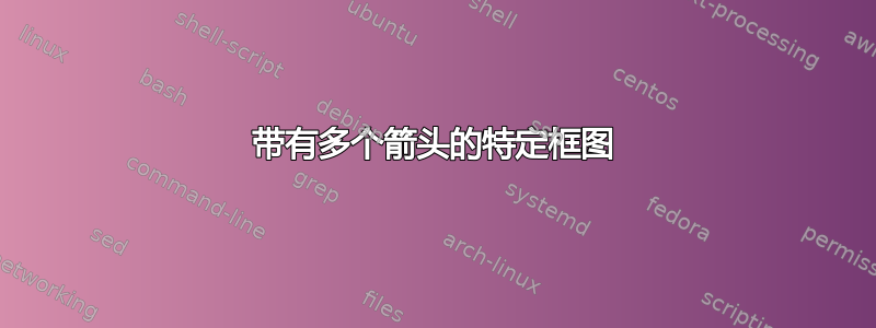
我以前从未画过框图。我尝试过构建此图,但找不到此类箭头的解决方案:有人能告诉我如何执行此操作吗?提前谢谢。
\tikzset{
decision/.style = {draw, text width=6.0em, text badly centered, node distance=3cm, minimum height=2.0em},
block/.style = {rectangle, draw,text width=6.0em, text centered, rounded corners=2ex,     minimum height=2.0em},
line/.style = {draw, -latex'},
cloud/.style = {draw, ellipse, node distance=3cm, minimum height=2em}
}

\begin{figure}[H]
\caption{bla}
\centering
\begin{tikzpicture}[node distance = 2cm, auto]

\coordinate (1) at (0,0);
\node [decision, right = 0cm of 1]  (2) {Antizipierte Einflüsse};
\node [decision, below left = .8cm and .1 of 2]  (3) {Sofortige Emotionen};
\node [decision, right = .8cm of 3] (4) {Entscheidung/\\Verhalten};
\node [decision, right = .8cm of 4] (5) {Erwartete\\Konsequenzen};
\node [decision, right  = .8cm of 5] (6) {Erwartete Emotionen};
\node [decision, below = .8cm of 3, node distance=1cm] (7){Zufällige Einflüsse};

\path [line] (2) -- node{b,c} (3);
\path [line] (3) -- node{d} (4);
\path [line] (4) -- node{e} (5);
\path [line] (5) -- node{f} (6);
\path [line] (7) -- node{g} (3);
\path [line] (6) -- node{c} (2);
\path [line] (6) -- node[near end,below=.5ex]{a} (4);
\end{tikzpicture}
\label{bla}
\end{figure}
答案1
一种可能性是,使用positioning库(这是可选的)来放置节点和to[out=<angle>,in=<angle>]弯曲箭头的语法:
\documentclass{article}
\usepackage{tikz}
\usetikzlibrary{positioning}

\begin{document}

\begin{tikzpicture}[
node distance=1.5cm and 1cm,
ar/.style={->,>=latex},
mynode/.style={
  draw,
  text width=2.5cm,
  minimum height=1cm,
  align=center
  }
]
\node[mynode] (ie) {Immediate emotions};
\node[mynode,right=of ie] (db) {Decision/ Behavior};
\node[mynode,right=of db] (ec) {Expected consequences};
\node[mynode,right=of ec] (ee) {Expected emotions};
\node[mynode,below=of ie] (ii) {Incidental influences};
\node[mynode,above right= 1.5cm and -1cm of ie] (ai) {Anticipatory influences};

\draw[ar]
  (ii) -- node[left] {g} (ie);
\draw[ar]
  (ie) -- node[above] {d} (db);
\draw[ar]
  (db) -- node[above] {e} (ec);
\draw[ar]
  (ec) -- node[above] {f} (ee);
\draw[ar]
  (ee.70) to[out=120,in=0] node[above] {c} (ai.east);
\draw[ar]
  (ai.west) to[out=180,in=90] node[left] {b,c} (ie.130);
\draw[ar]
  (ee.120) to[out=170,in=90,looseness=1.3] node[pos=0.93,left=3pt] {a} (db.north);
\draw[ar]
  (ec.120) to[out=100,in=-20] node[pos=0.1,left=3pt] {b} (ai.east);
\draw[ar]
  (ie.320) to[out=-40,in=200] node[pos=0.87,right=12pt] {i} (ee.south);
\draw[ar]
  (ie.320) to[out=-40,in=230] node[pos=0.87,right=6pt] {h} (ec.south);
\end{tikzpicture}

\end{document}

答案2
我相信 TikZ 是一个很好的解决方案,但作为有益的对比,这里有一个版本元帖子使用该boxes库。
你可以看到,与 TikZ 相比,在 MP 中管理好文本需要一些额外的工作,但事实并非如此那很难。我个人认为 MP 分别处理路径和标签的方式使用起来更简单一些,但这只是一种观点。
prologues := 3;
outputtemplate := "%j%c.eps";

input boxes;  % use the boxes library
defaultfont := "phvr8r"; % use Helvetica

% define a little macro to make the boxes easier (and also use Helvetica)
verbatimtex \font\sans="phvr8r"
\def\lbb#1\\#2.{\hbox to .9in{\hss\vbox to .4in{\vss
    \halign{&\hfil\sans ##\hfil\cr#1\cr#2\cr}\vss}\hss}}
etex

beginfig(1);
% define the boxes
boxit.ant(btex \lbb Anticipatory\\influences. etex);
boxit.imm(btex \lbb Immediate\\emotions.      etex);
boxit.dec(btex \lbb Decision/\\behaviour.     etex);
boxit.con(btex \lbb Expected\\consequences.   etex);
boxit.emo(btex \lbb Expected\\emotions.       etex);
boxit.inc(btex \lbb Incidental\\influences.   etex);

% layout the boxes by relating the centres to each other
ant.c = .8[imm.c,dec.c] + 64 up; inc.c + 64 up = imm.c;
imm.c - dec.c = dec.c - con.c = con.c - emo.c = 90 left;

% draw all the boxes, you could colour them etc here as well
forsuffixes x = ant, imm, dec, con, emo, inc:
  drawboxed(x);
  endfor

% define the connection paths
path p[];
p1 = emo.c {up} .. {left} con.n shifted 20up .. {down} dec.c cutbefore bpath emo cutafter bpath dec;
p2 = con.n {up} .. {left} ant.e;
p3 = emo.n {dir 110} .. {left} ant.e;
p23 = ant.w {left} .. {down} imm.c cutafter bpath imm;
p4 = imm.e -- dec.w;
p5 = dec.e -- con.w;
p6 = con.e -- emo.w;
p7 = inc.n -- imm.s;
p8 = imm.c {dir -40} .. {dir 70} con.c cutbefore bpath imm cutafter bpath con;
p9 = imm.c {dir -40} .. {dir 70} emo.c cutbefore bpath imm cutafter bpath emo;

% draw and label the paths, doing the crossing neatly
drawarrow p1; label.ulft("a", point 1.7 of p1);
undraw subpath(0.1,0.9) of p2 withpen pencircle scaled 3bp;
draw p2; label.urt("b", point 0.4 of p2);
drawarrow p3;  label.top ("c",   point 0.6 of p3);
drawarrow p23; label.ulft("b,c", point 0.7 of p23);
drawarrow p4;  label.top ("d",   point 0.5 of p4);
drawarrow p5;  label.top ("e",   point 0.5 of p5);
drawarrow p6;  label.top ("f",   point 0.5 of p6);
drawarrow p7;  label.rt  ("g",   point 0.5 of p7);
drawarrow p8;  label.ulft("h",   point 0.8 of p8);
drawarrow p9;  label.ulft("i",   point 0.8 of p9);

endfig;
end.

答案3
这是 MetaPost 的一次尝试 — — 大部分是在获得 Thruston 许可的情况下从他的程序中复制粘贴的 — — 旨在更轻松地管理标签。
主要的变化是使用latexmp包。我认为它使标签更容易实现,首先因为latexmp,正如其名称所暗示的那样,使用 LaTeX 来排版它们。
为此,它引入了textext函数来替代标志btex … etex。它更加灵活,因为它将字符串作为参数,允许包含在循环内,并且可以用作infont运算符的替代(即,将textextlabel选项键设置为enable,指令中的每个字符串label(" ", — )都会自动用 排版textext)。
它的缺点是您需要运行 MetaPost 程序两次才能生成标签。这也可以通过将mode选项键设置为 来实现自动化rerun。
因此,我为每个标记指令提供了textext函数,这些函数必须为每个框定义明确完成(因为它们不使用真实label指令),但可以为每个label指令隐式完成,因此保持不变。
由于该程序使用 LaTeX,因此 Helvetica 的使用是通过加载helvetLaTeX 包和指令来完成的
\renewcommand{\familydefault}{\sfdefault}
我还将\lbb命令重新定义为产生多行输出的 LaTeX 环境通过一个tabular环境。
\newenvironment{lbb}{\begin{tabular}{c}}{\end{tabular}}
Thruston 程序的其余部分保持不变,因此或多或少产生了相同的图形(绘制的框的尺寸并不完全相同,可能是因为 LaTeXtabular环境导致的间距不同)。
使用 LuaLaTeX 和luamplib包可以使标签管理变得更加容易,但我认为 LuaLaTeX 解决方案有点过于“具体”,不适合作为此类问题的答案(所使用的引擎尚未指定)。
prologues := 3;
outputtemplate := "%j%c.eps";

input boxes;  % use the boxes library
input latexmp;
setupLaTeXMP(textextlabel = enable,
   mode = rerun,
   packages = "helvet",
   preamble = ("\renewcommand{\familydefault}{\sfdefault}"
   & "\newenvironment{lbb}{\begin{tabular}{c}}{\end{tabular}}"));

beginfig(1);
% define the boxes
boxit.ant(textext("\begin{lbb} Anticipatory \\ influences \end{lbb}"));
boxit.imm(textext("\begin{lbb} Immediate \\ emotions \end{lbb}"));
boxit.dec(textext("\begin{lbb} Decision/ \\ behaviour \end{lbb}"));
boxit.con(textext("\begin{lbb} Expected \\ consequences \end{lbb}"));
boxit.emo(textext("\begin{lbb} Expected \\ emotions \end{lbb}"));
boxit.inc(textext("\begin{lbb} Incidental \\ influences \end{lbb}"));

% layout the boxes by relating the centres to each other
ant.c = .8[imm.c,dec.c] + 64 up; inc.c + 64 up = imm.c;
imm.c - dec.c = dec.c - con.c = con.c - emo.c = 90 left;

% draw all the boxes, you could colour them etc here as well
forsuffixes x = ant, imm, dec, con, emo, inc:
   drawboxed(x);
endfor

% define the connection paths
path p[];
p1 = emo.c {up} .. {left} con.n shifted 20up .. {down} dec.c cutbefore bpath emo cutafter bpath dec;
p2 = con.n {up} .. {left} ant.e;
p3 = emo.n {dir 110} .. {left} ant.e;
p23 = ant.w {left} .. {down} imm.c cutafter bpath imm;
p4 = imm.e -- dec.w;
p5 = dec.e -- con.w;
p6 = con.e -- emo.w;
p7 = inc.n -- imm.s;
p8 = imm.c {dir -40} .. {dir 70} con.c cutbefore bpath imm cutafter bpath con;
p9 = imm.c {dir -40} .. {dir 70} emo.c cutbefore bpath imm cutafter bpath emo;

% draw and label the paths, doing the crossing neatly
drawarrow p1; label.ulft("a", point 1.7 of p1);
undraw subpath(0.1,0.9) of p2 withpen pencircle scaled 3bp;
draw p2; label.urt("b", point 0.4 of p2);
drawarrow p3;  label.top ("c",   point 0.6 of p3);
drawarrow p23; label.ulft("b,c", point 0.7 of p23);
drawarrow p4;  label.top ("d",   point 0.5 of p4);
drawarrow p5;  label.top ("e",   point 0.5 of p5);
drawarrow p6;  label.top ("f",   point 0.5 of p6);
drawarrow p7;  label.rt  ("g",   point 0.5 of p7);
drawarrow p8;  label.ulft("h",   point 0.8 of p8);
drawarrow p9;  label.ulft("i",   point 0.8 of p9);

endfig;
end.
