

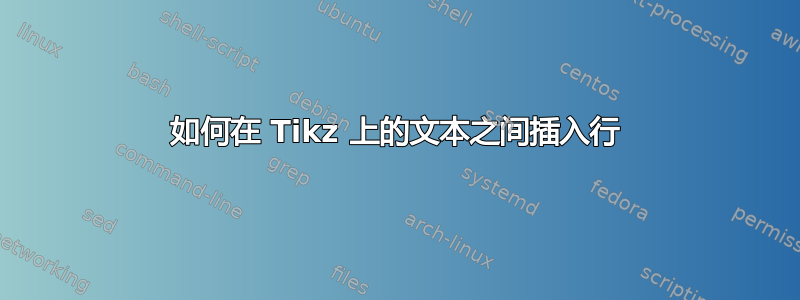
我是 Tikz 的新手,今天才开始使用它,遇到了一些困难,找不到解决办法。我正在根据以下示例制作一个框图例如:控制系统原理。我尝试根据自己的需要进行修改,例如在块上方添加文本\node [above of=controller, node distance=1.2cm] (MP:1) {$MP_1$};。我不知道这是否是正确的方法。我的理想情况是将此文本用左右箭头连接到引脚样式tin和tout/tin。由于tin和tout/tin我无法给它们命名,因此我无法使用该命令,\draw [draw,->] (tin) -- node [name=line] {} (MP:1);因此它将不起作用。我尝试插入\draw [->, right of=MP:1, node distance=1.5cm] {};但输出再次不正确。我查看了 Tikz 手册,并通过使用诸如这样的坐标找到了解决我的问题的方法\draw [<-] (20mm,10mm) -- (0mm,10mm);。结果再次不正确。
所以我的第一个问题是,我插入的文本是否正确,以便为文本提供名称作为参考,或者有没有更好的方法?我的第二个问题是,如果我正确插入文本,是否可以为 pinstyles 创建参考名称,如果不行,我该如何绘制线条?下面提供了我的代码示例以供测试,还有输出图片。
\documentclass{article}
\usepackage{tikz}
\usetikzlibrary{shapes,arrows}
\usepackage{pgfplots}
\pgfplotsset{compat=1.8}

\begin{document}

\tikzstyle{block} = [draw, rectangle, minimum height=2em, minimum width=5em] %fill=blue!20
\tikzstyle{sum} = [draw, circle, node distance=2.0cm, minimum size=6mm]
\tikzstyle{input} = [coordinate]
\tikzstyle{output} = [coordinate]
\tikzstyle{pinstyle} = [pin edge={to-,thin,black}]

\begin{figure}[!ht]
\begin{center}
\makebox[\textwidth][c]{
\begin{tikzpicture}[auto, node distance=1.5cm,>=latex']
\node [input, name=input] {};
\node [sum, right of=input, pin={[pinstyle]above:$t_{in}$}, node distance=1.5cm] (sum) {MP};
\draw [draw,->] (input) -- node [name=begging] {UE} (sum);
\node [block, right of=sum, node distance=2.0cm] (controller) {Node B};
% Text above of GGSN (MP1)
\node [above of=controller, node distance=1.2cm] (MP:1) {$MP_1$};
\draw [<-] (20mm,10mm) -- (0mm,10mm);
%\draw [->, right of=MP:1, node distance=1.5cm] {};
\draw [->] (sum) -- node {} (controller);
\node [sum, right of=controller, pin={[pinstyle]above:$t_{out}/t_{in}$}, node distance=2.0cm] (sum_2) {MP};
\draw [->] (controller) -- node [name=u] {} (sum_2);
\node [block, right of=sum_2, node distance=2.0cm] (controller_2) {RNC};
% Text above of GGSN (MP2)
\node [above of=controller_2, node distance=1.2cm] (MP:2) {$MP_2$};
\draw [->] (sum_2) -- node [name=u2] {} (controller_2);
\node [sum, right of=controller_2, pin={[pinstyle]above:$t_{out}/t_{in}$}, node distance=2.0cm] (sum_3) {MP};
\draw [->] (controller_2) -- node [name=u3] {} (sum_3);
\node [block, right of=sum_3, node distance=2.0cm] (controller_3) {SGSN};
% Text above of GGSN (MP3)
\node [above of=controller_3, node distance=1.2cm] (MP:3) {$MP_3$};
\draw [->] (sum_3) -- node [name=u4] {} (controller_3);
\node [sum, right of=controller_3, pin={[pinstyle]above:$t_{out}/t_{in}$}, node distance=2.0cm] (sum_4) {MP};
\draw [->] (controller_3) -- node [name=u5] {} (sum_4);
\node [block, right of=sum_4, node distance=2.0cm] (controller_4) {GGSN};
% Text above of GGSN (MP4)
\node [above of=controller_4, node distance=1.2cm] (MP:4) {$MP_4$};
\draw [->] (sum_4) -- node [name=u6] {} (controller_4);
\node [sum, right of=controller_4, pin={[pinstyle]above:$t_{out}$}, node distance=2.0cm] (sum_5) {MP};
\draw [->] (controller_4) -- node [name=u8] {} (sum_5);
\node [output, right of=sum_5] (output) {};
\draw [->] (sum_5) -- node [name=end] {PDN}(output);
\node [block, above of=sum_3, node distance=2.5cm] (pipeline) {Pipeline};
\draw [->] (begging) |- (pipeline);
\draw [->] (pipeline) -| (end);
\end{tikzpicture} } % End of makebox
\caption{Test}
\label{fig:blockdiagram}
\end{center}
\end{figure}

\end{document}

答案1
改良版:
我将旧的语法改为
\tikzsetstyle更合适的\tikzset语法。我建议您不要
:在节点名称中使用它,因为该:运算符应用于节点名称时具有特殊含义。我加载了该
positioning库并将弃用的of=语法更改为该=of语法(请注意生成的代码中的经济性)。我使用了节点样式而不是大头针
mytext;这样可以获得更好的结果。改进空间:也许在这里使用链会简化代码。这留作练习。
代码:
\documentclass{article}
\usepackage{tikz}
\usetikzlibrary{shapes,arrows,positioning}

\begin{document}

\tikzset{
block/.style={
  draw,
  rectangle,
  minimum height=2em,
  minimum width=5em
  },
sum/.style={
  draw,
  circle,
  minimum size=6mm
  },
input/.style={coordinate},
output/.style={coordinate},
mytext/.style={
  draw,
  text depth=4pt,
  text height=10pt
  }
}
\begin{figure}[!ht]
\begin{center}
\makebox[\textwidth][c]{%
\begin{tikzpicture}[auto,node distance=1cm and 0.8cm,>=latex']
\node[
  input,
  name=input] {};
\node[
  sum,
  right = of input
  ]
  (sum) {MP};
\node[
  mytext,
  above=of sum.center,
  name=tin1
  ]
  {$t_{in}$};
\draw[->]
  (input) -- node [name=begging] {UE} (sum);
\node[
  block,
  right = of sum
  ]
  (controller) {Node B};
% Text above of GGSN (MP1)
\node[
  mytext,
  above = of controller.center
  ]
  (MP1) {$MP_1$};
%\draw [->, right = of MP:1, node distance=1.5cm] {};
\draw[->]
  (sum) -- node {} (controller);
\node[
  sum,
  right = of controller
  ]
  (sum_2) {MP};
\node[
  mytext,
  above=of sum_2.center,
  name=toti1
  ]
  {$t_{out}/t_{in}$};
\draw[->]
  (controller) -- node [name=u] {} (sum_2);
\node[
  block,
  right = of sum_2
  ]
  (controller_2) {RNC};
% Text above of GGSN (MP2)
\node[
  mytext,
  above = of controller_2.center
  ]
  (MP2) {$MP_2$};
\draw[->]
  (sum_2) -- node [name=u2] {} (controller_2);
\node[
  sum,
  right = of controller_2,
  ]
  (sum_3) {MP};
\node[
  mytext,
  above=of sum_3.center,
  name=toti2
  ]
  {$t_{out}/t_{in}$};
\draw[->]
  (controller_2) -- node [name=u3] {} (sum_3);
\node[
  block,
  right = of sum_3
  ]
  (controller_3) {SGSN};
% Text above of GGSN (MP3)
\node[
  mytext,
  above = of controller_3.center
  ]
  (MP3) {$MP_3$};
\draw[->]
  (sum_3) -- node [name=u4] {} (controller_3);
\node[
  sum,
  right = of controller_3,
  ]
  (sum_4) {MP};
\node[
  mytext,
  above=of sum_4.center,
  name=  toti3
  ] {$t_{out}/t_{in}$};
\draw[->]
  (controller_3) -- node [name=u5] {} (sum_4);
\node[
  block,
  right = of sum_4
  ]
  (controller_4) {GGSN};
% Text above of GGSN (MP4)
\node[
  mytext,
  above = of controller_4.center
  ]
  (MP4) {$MP_4$};
\draw[->]
  (sum_4) -- node [name=u6] {} (controller_4);
\node[
  sum,
  right = of controller_4
  ]
  (sum_5) {MP};
\node[
  mytext,
  above=of sum_5.center,
  name=tout1
  ]
  {$t_{out}$};
\draw[->]
  (controller_4) -- node [name=u8] {} (sum_5);
\node[
  output,
  right = of sum_5
  ]
  (output) {};
\draw[->]
  (sum_5) -- node [name=end] {PDN}(output);
\node[
  block,
  above = 2cm of sum_3
  ]
  (pipeline) {Pipeline};
\draw[->]
  (begging) |- (pipeline);
\draw[->]
  (pipeline) -| (end);

\draw[->]
  (tin1) -- (sum);
\draw[->]
  (toti1) -- (sum_2);
\draw[->]
  (toti2) -- (sum_3);
\draw[->]
  (toti3) -- (sum_4);
\draw[->]
  (tout1) -- (sum_5);

\draw[<->]
  (tin1) -- (MP1);
\draw[<->]
  (MP1.east) -- (toti1.west|-MP1.east);
\draw[<->]
  (toti1.east) -- (MP2.west|-toti1.east);
\draw[<->]
  (MP2.east) -- (toti2.west|-MP2.east);
\draw[<->]
  (toti2.east) -- (MP3.west|-toti2.east);
\draw[<->]
  (MP3.east) -- (toti3.west|-MP3.east);
\draw[<->]
  (toti3.east) -- (MP4.west|-toti3.east);
\draw[<->]
  (MP4.east) -- (tout1.west|-MP4.east);
\end{tikzpicture}} % End of makebox
\caption{Test}
\label{fig:blockdiagram}
\end{center}
\end{figure}

\end{document}

从样式中删除该draw选项mytext。
初始版本:
Apin只是一个特殊节点,因此您可以name=<string>给它们起一个名字以便于连接它们:
\documentclass{article}
\usepackage{tikz}
\usetikzlibrary{shapes,arrows}

\begin{document}

\tikzset{
block/.style={
  draw,
  rectangle,
  minimum height=2em,
  minimum width=5em
  },
sum/.style={
  draw,
  circle,
  node distance=2.0cm,
  minimum size=6mm
  },
input/.style={coordinate},
output/.style={coordinate},
pinstyle/.style={
  pin edge={to-,thin,black}
  }
}
\begin{figure}[!ht]
\begin{center}
\makebox[\textwidth][c]{
\begin{tikzpicture}[auto, node distance=1.5cm,>=latex']
\node [input, name=input] {};
\node [sum, right of=input, pin={[pinstyle,name={tin1}]above:$t_{in}$}, node distance=1.5cm] (sum) {MP};
\draw [draw,->] (input) -- node [name=begging] {UE} (sum);
\node [block, right of=sum, node distance=2.0cm] (controller) {Node B};
% Text above of GGSN (MP1)
\node [above of=controller, node distance=1.2cm] (MP1) {$MP_1$};
\draw [<-] (20mm,10mm) -- (0mm,10mm);
%\draw [->, right of=MP:1, node distance=1.5cm] {};
\draw [->] (sum) -- node {} (controller);
\node [sum, right of=controller, pin={[pinstyle,name=toti1]above:$t_{out}/t_{in}$}, node distance=2.0cm] (sum_2) {MP};
\draw [->] (controller) -- node [name=u] {} (sum_2);
\node [block, right of=sum_2, node distance=2.0cm] (controller_2) {RNC};
% Text above of GGSN (MP2)
\node [above of=controller_2, node distance=1.2cm] (MP2) {$MP_2$};
\draw [->] (sum_2) -- node [name=u2] {} (controller_2);
\node [sum, right of=controller_2, pin={[pinstyle,name=toti2]above:$t_{out}/t_{in}$}, node distance=2.0cm] (sum_3) {MP};
\draw [->] (controller_2) -- node [name=u3] {} (sum_3);
\node [block, right of=sum_3, node distance=2.0cm] (controller_3) {SGSN};
% Text above of GGSN (MP3)
\node [above of=controller_3, node distance=1.2cm] (MP3) {$MP_3$};
\draw [->] (sum_3) -- node [name=u4] {} (controller_3);
\node [sum, right of=controller_3, pin={[pinstyle,name=toti3]above:$t_{out}/t_{in}$}, node distance=2.0cm] (sum_4) {MP};
\draw [->] (controller_3) -- node [name=u5] {} (sum_4);
\node [block, right of=sum_4, node distance=2.0cm] (controller_4) {GGSN};
% Text above of GGSN (MP4)
\node [above of=controller_4, node distance=1.2cm] (MP4) {$MP_4$};
\draw [->] (sum_4) -- node [name=u6] {} (controller_4);
\node [sum, right of=controller_4, pin={[pinstyle,name=tout1]above:$t_{out}$}, node distance=2.0cm] (sum_5) {MP};
\draw [->] (controller_4) -- node [name=u8] {} (sum_5);
\node [output, right of=sum_5] (output) {};
\draw [->] (sum_5) -- node [name=end] {PDN}(output);
\node [block, above of=sum_3, node distance=2.5cm] (pipeline) {Pipeline};
\draw [->] (begging) |- (pipeline);
\draw [->] (pipeline) -| (end);

\draw[<->] (tin1.east) -- (MP1.west|-tin1.east);
\draw[<->] (MP1.east) -- (toti1.west|-MP1.east);
\draw[<->] (toti1.east) -- (MP2.west|-toti1.east);
\draw[<->] (MP2.east) -- (toti2.west|-MP2.east);
\draw[<->] (toti2.east) -- (MP3.west|-toti2.east);
\draw[<->] (MP3.east) -- (toti3.west|-MP3.east);
\draw[<->] (toti3.east) -- (MP4.west|-toti3.east);
\draw[<->] (MP4.east) -- (tout1.west|-MP4.east);
\end{tikzpicture} } % End of makebox
\caption{Test}
\label{fig:blockdiagram}
\end{center}
\end{figure}

\end{document}

我将旧语法改成了\tikzsetstyle更合适的\tikzset语法。另外,我建议您不要:在节点名称中使用,因为该:运算符在应用于节点名称时具有特殊含义。
我还建议您加载定位库并将弃用的of=语法更改为该=of语法。
答案2
Gonzalo 已经给出了一个很好的答案,但是对于这样的常规的方案matrix节点是一个不错的选择。您不需要手动定位每个节点,并且使用matrix of nodes选项(您需要加载matrix库)可以节省大量输入。
\documentclass{article}
\usepackage{tikz}
\usepackage{adjustbox}
\usetikzlibrary{shapes,matrix,arrows}

\begin{document}

\tikzset{
block/.style={
  draw,
  rectangle,
  minimum height=2em,
  minimum width=5em
  },
sum/.style={
  draw,
  circle,
  minimum size=6mm
  },
input/.style={coordinate},
output/.style={coordinate},
mytext/.style={
  text depth=4pt,
  text height=10pt
  }
}

\begin{figure}[!ht]
\centering
\adjustbox{width=\linewidth}{
\begin{tikzpicture}[>=latex']

\matrix (D) [matrix of nodes,
                column sep=1cm,
                row sep=0.8cm,
                row 1/.style={nodes={block,anchor=center}},
                row 3/.style={nodes={block,anchor=center}},
                row 2/.append style={nodes={mytext,anchor=center}},
                ]
{
& & & & & Pipeline \\
& $t_in$ & $MP_1$ & $t_{out}/t_{in}$ & $MP_2$ & $t_{out}/t_{in}$ & $MP_3$ & $t_{out}/t_{in}$ & $MP_4$ & $t_{out}$ & \\
|[input]| &|[sum]| MP & Node B &|[sum]| MP & RNC &|[sum]| MP & SGSN &|[sum]| MP & GGSN &|[sum]| MP & |[input]|\\
};

\foreach \i [remember=\i as \lasti (initially 1)] in {2,...,11}
\draw[->] (D-3-\lasti)--(D-3-\i);

\foreach \i [remember=\i as \lasti (initially 2)] in {3,...,10}
\draw[<->] (D-2-\lasti)--(D-2-\i);

\foreach \i in {2,4,6,8,10}
\draw[->] (D-2-\i)--(D-3-\i);

\path (D-3-1)--(D-3-2) node [above,midway] (UE) {UE};
\path (D-3-10)--(D-3-11) node [above,midway] (PDN) {PDN};
\draw[->] (UE) |- (D-1-6);
\draw[<-] (PDN) |- (D-1-6);

\end{tikzpicture}}
\caption{Test}
\label{fig:blockdiagram}
\end{figure}

\end{document}
