

Tikz 有很多有用的数字电路元件,有基本的也有复杂的。在这里,我需要一些我自己发明的,甚至不一定是最方便的。但让我们举一个相当方便的例子:量级比较器。
我想要这个幅度比较器我的任务的组件,其信号端口定义为anchors。我可以制作一个带有端口标签和名称的盒子,但那是不够!
我也需要展示内部情况。细节不应超出门的范围,我不需要晶体管,但我确实需要门。
以下是我目前掌握的内容,其中大部分都是从这个(著名的?)数据触发器示例:
\makeatletter

% Magnitude Comparator (magn comparator) shape
\pgfdeclareshape{magn comparator}
{
    % The 'minimum width' and 'minimum height' keys, not the content, determine
    % the size
    \savedanchor\northeast
    {%
        \pgfmathsetlength\pgf@x{\pgfshapeminwidth}%
        \pgfmathsetlength\pgf@y{\pgfshapeminheight}%
        \pgf@x=0.5\pgf@x
        \pgf@y=0.5\pgf@y
    }
    % This is redundant, but makes some things easier:
    \savedanchor\southwest
    {%
        \pgfmathsetlength\pgf@x{\pgfshapeminwidth}%
        \pgfmathsetlength\pgf@y{\pgfshapeminheight}%
        \pgf@x=-0.5\pgf@x
        \pgf@y=-0.5\pgf@y
    }
    % Inherit from rectangle
    \inheritanchorborder[from=rectangle]

    % Define same anchor a normal rectangle has
    \anchor{center}{\pgfpointorigin}
    \anchor{north}{\northeast \pgf@x=0pt}
    \anchor{east}{\northeast \pgf@y=0pt}
    \anchor{south}{\southwest \pgf@x=0pt}
    \anchor{west}{\southwest \pgf@y=0pt}
    \anchor{north east}{\northeast}
    \anchor{north west}{\northeast \pgf@x=-\pgf@x}
    \anchor{south west}{\southwest}
    \anchor{south east}{\southwest \pgf@x=-\pgf@x}
    \anchor{text}
    {
        \pgfpointorigin
        \advance\pgf@x by -.5\wd\pgfnodeparttextbox%
        \advance\pgf@y by -.5\ht\pgfnodeparttextbox%
        \advance\pgf@y by +.5\dp\pgfnodeparttextbox%
    }

    % Define anchors for input signal ports
    \anchor{input gt}
    {
        \pgf@process{\southwest}%
        \pgf@y=-.5\pgf@y%
    }
    \anchor{input eq}
    {
        \pgf@process{\southwest}%
        \pgf@y=0pt%
    }
    \anchor{input lt}
    {
        \pgf@process{\southwest}%
        \pgf@y=.5\pgf@y%
    }
    \anchor{input a}
    {
        \pgf@process{\northeast}%
        \pgf@x=-.3\pgf@x%
    }
    \anchor{input b}
    {
        \pgf@process{\northeast}%
        \pgf@x=.3\pgf@x%
    }

    % Define anchors for output signal ports
    \anchor{output gt}
    {
        \pgf@process{\northeast}%
        \pgf@y=.5\pgf@y%
    }
    \anchor{output eq}
    {
        \pgf@process{\northeast}%
        \pgf@y=0pt%
    }
    \anchor{output lt}
    {
        \pgf@process{\northeast}%
        \pgf@y=-.5\pgf@y%
    }

    % Draw the rectangle box and the port labels
    \backgroundpath
    {
        % Rectangle box
        \pgfpathrectanglecorners{\southwest}{\northeast}
        % \node [and gate] (kek) at (0, 0) {};
    }
}

% Define default style for this node
\tikzset
{
    every magn comparator node/.style =
    {
        draw,
        minimum width = 2cm,
        minimum height = 2cm,
        thick,
        inner sep = 1mm,
        outer sep = 0pt,
        cap = round
    }
}

\makeatother
这是一个单独的文件,我将其包含在我的主 LaTeX 文件的序言中。
这里没有门,它只是画出盒子。我尝试以我通常的方式在这个\pgfdeclareshape东西外面放置一个随机的 AND 门,当然没有成功。我把那个尝试注释掉了。
我应该有一种方法可以在现有形状的基础上定义更多形状。它是什么?
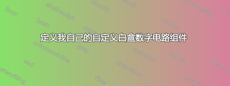
编辑:我希望手中有这样的东西,我应该能够放置它,并且我可以轻松地将其端口作为锚点到达,类似于 AND/OR/NOR/XOR/NAND 门的情况:

请注意,盒子内部实际上并不起到幅度比较器的作用,它只是我所期望的一个虚拟示例。
答案1
取决于您的用例的复杂性以及您需要多少个形状……这里有一个开始。
答案如下:
借用了(仅仅是借用了形状和锚点)
rectangle ee的定义的形状声明。circuits.eerectangle.input.output我也借用了链接示例用于形状定义内的文本。锚点用设置
\pgfpointlineattime(这类似于pos沿直线的键,或符号内的因子calc)($(<p1>)!<factor>!(<p2>)$)。如果您有更多这样的形状,并且需要沿矩形边框设置多个不同的锚点,则可以使用形状声明中的 fey 键和循环进行序列化。这也适用于文本。
现在我们有了带有锚点和文本的形状,我们可以使用它了。对于合适的电路形状,我们用 声明一个符号,
circuit declare symbol并用 进行设置set <symbol name> graphic。键
circuit symbol size设置minimum width和minimum height相对于circuit symbol unit(引擎盖下的 TeX 尺寸)。这使得它相对于其他电路符号可扩展。transform shape需要键来使其沿circuits'to路径旋转。path picture使用来自的建议代码我的另一个答案。设置随节点旋转和缩放的局部坐标系:坐标(0, 0)位于节点中心。X向量指向east(=output),是指向北锚的向量。这对于坐标规范很重要,(left:.2)因为它使用了.2节点水平尺寸的一半和应用的旋转。内部的电路符号
path picture获得选项gray(线条也是如此),并且circuit symbol unit=.1cm会将符号缩小到合适的大小。可能需要调整此值以获得正确的大小。也可以使其依赖于上述局部坐标系,其尺寸为\pgf@xx和\pgf@yy。显然,如果您需要具有相同锚点和连接布局但具有不同门的多个符号,则可以根据三个值键使形状定义具有可延展性,在本例中将其设置为
not gate、nand gate和nor gate。
我已经用过我的paths.ortho图书馆对于内部的连接path picture。显然,您可以使用任何方式连接这些线路。
代码
\documentclass[tikz]{standalone}
\usetikzlibrary{circuits.ee,circuits.logic.US,paths.ortho}
\makeatletter
\pgfdeclareshape{my complicated box}{%
  \inheritsavedanchors[from=rectangle ee]
  \inheritanchor[from=rectangle ee]{center}
  \inheritanchor[from=rectangle ee]{north}
  \inheritanchor[from=rectangle ee]{south}
  \inheritanchor[from=rectangle ee]{east}
  \inheritanchor[from=rectangle ee]{west}
  \inheritanchor[from=rectangle ee]{north east}
  \inheritanchor[from=rectangle ee]{north west}
  \inheritanchor[from=rectangle ee]{south east}
  \inheritanchor[from=rectangle ee]{south west}
  \inheritanchor[from=rectangle ee]{input}
  \inheritanchor[from=rectangle ee]{output}
  \inheritanchorborder[from=rectangle ee]
  \inheritbackgroundpath[from=rectangle ee]
  \anchor{eq in} {\pgf@sh@reanchor{\pgf@sm@shape@name}{input}}
  \anchor{eq out}{\pgf@sh@reanchor{\pgf@sm@shape@name}{output}}
  \anchor{lt in}{%
    \pgfpointlineattime{.2}{\southwest}
    {\southwest\pgf@xc\pgf@x\northeast\pgf@x\pgf@xc}}
  \anchor{gt in}{%
    \pgfpointlineattime{.8}{\southwest}
    {\southwest\pgf@xc\pgf@x\northeast\pgf@x\pgf@xc}}
  \anchor{gt out}{%
    \pgfpointlineattime{.3}{\northeast}
    {\southwest\pgf@yc\pgf@y\northeast\pgf@y\pgf@yc}}
  \anchor{lt out}{%
    \pgfpointlineattime{.7}{\northeast}
    {\southwest\pgf@yc\pgf@y\northeast\pgf@y\pgf@yc}}
  \anchor{a}{%
    \pgfpointlineattime{.4}
      {\southwest\pgf@xc\pgf@x\northeast\pgf@x\pgf@xc}{\northeast}}
  \anchor{b}{%
    \pgfpointlineattime{.6}
      {\southwest\pgf@xc\pgf@x\northeast\pgf@x\pgf@xc}{\northeast}}
  \beforebackgroundpath{%
    \begingroup
      \tikzset{my complicated box/labels/.try}\tikz@textfont
      \pgf@sh@reanchor{\pgf@sm@shape@name}{eq in}
      \pgftext[at=\pgfqpoint{\pgf@x}{\pgf@y},left,%
                x=\pgfkeysvalueof{/pgf/inner xsep}]{$\mathrm{eq}_{\mathrm{in}}$}
      \pgf@sh@reanchor{\pgf@sm@shape@name}{eq out}
      \pgftext[at=\pgfqpoint{\pgf@x}{\pgf@y},right,%
                x=-\pgfkeysvalueof{/pgf/inner xsep}]{$\mathrm{eq}_{\mathrm{out}}$}
      \pgf@sh@reanchor{\pgf@sm@shape@name}{gt in}
      \pgftext[at=\pgfqpoint{\pgf@x}{\pgf@y},left,%
                x=\pgfkeysvalueof{/pgf/inner xsep}]{$\mathrm{gt}_{\mathrm{in}}$}
      \pgf@sh@reanchor{\pgf@sm@shape@name}{gt out}
      \pgftext[at=\pgfqpoint{\pgf@x}{\pgf@y},right,%
                x=-\pgfkeysvalueof{/pgf/inner xsep}]{$\mathrm{gt}_{\mathrm{out}}$}
      \pgf@sh@reanchor{\pgf@sm@shape@name}{lt in}
      \pgftext[at=\pgfqpoint{\pgf@x}{\pgf@y},left,%
                x=\pgfkeysvalueof{/pgf/inner xsep}]{$\mathrm{lt}_{\mathrm{in}}$}
      \pgf@sh@reanchor{\pgf@sm@shape@name}{lt out}
      \pgftext[at=\pgfqpoint{\pgf@x}{\pgf@y},right,%
                x=-\pgfkeysvalueof{/pgf/inner xsep}]{$\mathrm{lt}_{\mathrm{out}}$}
      \pgf@sh@reanchor{\pgf@sm@shape@name}{a}
      \pgftext[at=\pgfqpoint{\pgf@x}{\pgf@y},top,%
                y=-\pgfkeysvalueof{/pgf/inner ysep}]{a\vphantom{b}}
      \pgf@sh@reanchor{\pgf@sm@shape@name}{b}
      \pgftext[at=\pgfqpoint{\pgf@x}{\pgf@y},top,%
                y=-\pgfkeysvalueof{/pgf/inner ysep}]{b}
    \endgroup}
}
\makeatother
\tikzset{my complicated box/labels/.style={font=\footnotesize, inner sep=.1667em}}
\tikzset{
  circuit declare symbol=my complicated symbol,
  set my complicated symbol graphic={
    draw, shape=my complicated box, circuit symbol size=width 10 height 8,
    transform shape,
    path picture={
      \expandafter\let\expandafter\tfn\csname tikz@fig@name\endcsname
      \pgftransformshift{\pgfpointanchor{\tfn}{center}}%
      \pgfsetxvec{\pgfpointdiff{\pgfpointanchor{\tfn}{center}}
                 {\pgfpointanchor{\tfn}{east}}}%
      \pgfsetyvec{\pgfpointdiff{\pgfpointanchor{\tfn}{center}}
                 {\pgfpointanchor{\tfn}{north}}}
      \tikzset{every circuit symbol/.append style={circuit symbol unit=.1cm, gray}}
      \path[thin, draw=gray]
        (\tfn.eq in) to[not gate=near end] (\tfn.eq out)
        (\tfn.lt out) to ++ (left:.2)
          node[anchor=output, logic gate inputs=nn, nand gate] (\tfn-nand) {}
        (\tfn-nand.input 2) to[-|-=.6] (\tfn.lt in)
        (\tfn-nand.input 1) to[-|] (\tfn.a)
        (\tfn.gt out) to ++ (left:.2)
          node[anchor=output, logic gate inputs=nn, nor gate] (\tfn-nor) {}
        (\tfn-nor.input 2) to[-|-=.6] (\tfn.gt in)
        (\tfn-nor.input 1) to[-|] (\tfn.b);
    }},
}
\begin{document}
\begin{tikzpicture}[circuit logic US]
\draw (0,0) to[my complicated symbol] ++ (30:4);
\end{tikzpicture}
\end{document}
输出

答案2
一个可能的解决方案是pics。它很难用于pic-anchors定位(固定 TiKZ 图片),但它们可以作为在它们之间建立联系的参考点。
\documentclass[tikz,border=2mm]{standalone}

\usetikzlibrary{positioning,circuits.logic.US, fit}

\tikzset{
    mycircuit/.pic={
        \begin{scope}[circuit logic US]
        \node[gray, thick, draw, nor gate] (-gt) at (2,0.75) {};
        \node[gray, thick, draw, not gate] (-eq) at (2,0) {};
        \node[gray, thick, draw, nand gate] (-lt) at (2,-0.75) {};

        \draw[gray] (-gt.output)--++(3mm,0)
             coordinate[label={[black]left:$\mathrm{gt}_\mathrm{out}$}] (-gtout);

        \draw[gray] (-eq.output)--(-eq.output-|-gtout)
             coordinate[label={[black]left:$\mathrm{eq}_\mathrm{out}$}] (-eqout);

        \draw[gray] (-lt.output)--(-lt.output-|-gtout)
             coordinate[label={[black]left:$\mathrm{lt}_\mathrm{out}$}] (-eqout);

        \draw[gray] (-gt.input 1)-|++(-3mm,.5cm)
             coordinate[label={[black]below:$\mathrm{b}$}] (-b);

        \draw[gray] (-lt.input 1)-|([xshift=-6mm]-b.center)
             coordinate[label={[black]below:$\mathrm{a}$}] (-a);

        \draw[gray] (-eq.input)--++(-2cm,0)
             coordinate[label={[black]right:$\mathrm{eq}_\mathrm{in}$}] (-eqin);

        \draw[gray] (-gt.input 2)--++(-1.2cm,0) |- ([yshift=1cm]-eqin.center)
             coordinate[label={[black]right:$\mathrm{gt}_\mathrm{in}$}] (-gtin);

        \draw[gray] (-lt.input 2)--++(-1.2cm,0) |- ([yshift=-1cm]-eqin.center)
             coordinate[label={[black]right:$\mathrm{lt}_\mathrm{in}$}] (-ltin);

        \node[draw, fit={(-ltin) (-b) ([yshift=-.5cm]-lt.input 2) (-gtout)},
              inner sep=0pt] (-box) {};
        \end{scope}
    }}

\begin{document}
\begin{tikzpicture}

\pic (a) at (0,0) {mycircuit};

\pic (b) at (5,1) {mycircuit};

\draw (a-gtout) -- (b-gtin);
\draw ([yshift=2cm]a-a) coordinate (aux)--(a-a);
\draw ([yshift=-5mm]aux)-|(b-a);
\end{tikzpicture}
\end{document}
