

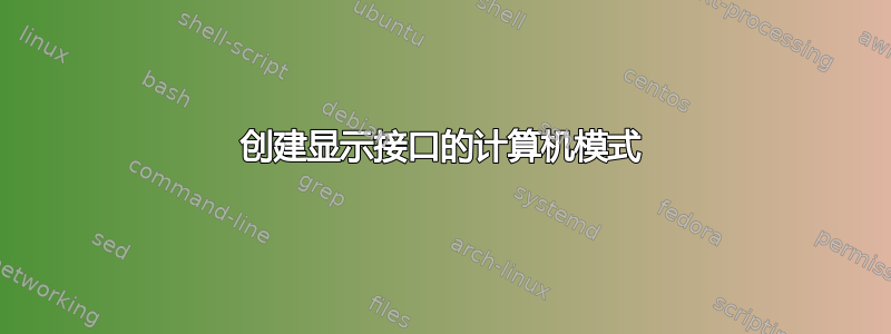
我想制作一个计算机架构的模式,将接口表示为其他盒子内的小盒子,如下所示:

所以我不知道该用什么方法画出这样的方框tikz,或者用其他什么方法。有什么想法吗?
答案1
这是一个可能的解决方案:
编辑:微调边界框。

\documentclass[tikz,border=10pt]{standalone}
\usetikzlibrary{positioning, arrows, chains, shapes}

\begin{document}
\begin{tikzpicture}[auto,
    >=stealth', node distance = 1.2cm and 1cm,
    every node/.style={minimum height=1.5em, minimum width=8ex},
    a/.style={draw, thick, anchor=center},
    b/.style={a, regular polygon,regular polygon sides=4, rounded corners},
    c/.style={b,circle},
    start chain=0 going right, ch0/.style={on chain=0, join},
    start chain=1 going right, ch1/.style={on chain=1, join},
    start chain=2 going right, ch2/.style={on chain=2, join},
    start chain=3 going right, ch3/.style={on chain=3, join},
    arrow/.style={<->, thick,shorten >=1pt},
    every join/.style={arrow},
    shiftn/.style={xshift={.5\pgflinewidth},yshift=-{.5\pgflinewidth}},
    shifts/.style={xshift=-{.5\pgflinewidth},yshift={.5\pgflinewidth}},
    s/.style={xshift=4pt,yshift=-4pt},
    ]

    \node[a] (eth0) {eth0};
    \node[b, right=2cm of eth0] (iptables) {iptables};
    \node[a, above right=2.4cm and 3cm of iptables.center, ch0] (veth0) {veth0};
    \node[a, below=of veth0, ch1] (veth1) {veth1};
    \node[a, below=of veth1, ch2] (veth2) {veth2};
    \node[a, below=of veth2, ch3] (veth3) {veth3};
    \node[a, anchor=north] (eth1) at (iptables|-veth3.south) {eth1};

    \coordinate (c) at (eth0.west|-veth0.north);
    \node[above=1pt of c, anchor=south west] (lroot) {netns root};

    \draw[arrow] (iptables) -- (veth0);
    \draw[arrow] (iptables) -- (veth1);
    \draw[arrow] (iptables) -- (veth2);
    \draw[arrow] (iptables) -- (veth3);
    \path[draw] (eth0) edge[arrow, ->] (iptables)
                (iptables) edge[arrow, ->] (eth1);

    \draw[thick] ([shiftn]current bounding box.north west) rectangle
        ([shifts]current bounding box.south east);
    \node[above=of lroot.south west, anchor=south west] {Gateway};

    \begin{scope}[node distance=2cm]
        \node[a, right=of veth0, ch0] (main0) {main};
        \node[a, right=of veth1, ch1] (main1) {main};
        \node[a, right=of veth2, ch2] (main2) {main};
        \node[a, right=of veth3, ch3] (main3) {main};
    \end{scope}

    \node[a, right=of main0, ch0] (tun0) {tun0};
    \node[a, right=of main1, ch1] (tun1) {tun0};
    \node[a, right=of main2, ch2] (tun2) {tun0};
    \node[a, right=of main3, ch3] (tun3) {tun0};

    \begin{scope}[local bounding box=bb0]
        \node[above=1pt of main0.north west, anchor=south west] {netns vpn0};
        \node[c, right=of tun0, ch0] (ssh0) {SSH};
    \end{scope}

    \begin{scope}[local bounding box=bb1]
        \node[above=1pt of main1.north west, anchor=south west] {netns vpn1};
        \node[c, right=of tun1, ch1] (ssh1) {SSH};
    \end{scope}

    \begin{scope}[local bounding box=bb2]
        \node[above=1pt of main2.north west, anchor=south west] {netns vpn2};
        \node[c, right=of tun2, ch2] (ssh2) {SSH};
    \end{scope}

    \begin{scope}[local bounding box=bb3]
        \node[above=1pt of main3.north west, anchor=south west] {netns vpn3};
        \node[c, right=of tun3, ch3] (ssh3) {SSH};
    \end{scope}

    \draw[thick] ([xshift={.25\pgflinewidth},yshift=-{.5\pgflinewidth}]bb0.north west)
        rectangle ([s]bb0.south east);
    \draw[thick] ([xshift={.25\pgflinewidth},yshift=-{.5\pgflinewidth}]bb1.north west)
        rectangle ([s]bb1.south east);
    \draw[thick] ([xshift={.25\pgflinewidth},yshift=-{.5\pgflinewidth}]bb2.north west)
        rectangle ([s]bb2.south east);
    \draw[thick] ([xshift={.25\pgflinewidth},yshift=-{.5\pgflinewidth}]bb3.north west)
        rectangle ([s]bb3.south east);

    \draw[thick] ([shiftn]current bounding box.north west) rectangle
         ([xshift=.5cm, yshift={.5\pgflinewidth}]current bounding box.south east);

    \node[below=8pt of eth1, font=\Large] {Client side};
    \node[left=8pt of eth0, font=\Large] {Support side};
\end{tikzpicture}
\end{document}