

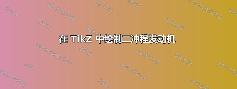
我试图重现这幅图像:

我得到了以下 MWE:
\documentclass[border=5pt,tikz]{standalone}
\usepackage[utf8]{inputenc}
\usetikzlibrary{calc,snakes}
\begin{document}
    \begin{tikzpicture}[every node/.style={font=\tiny\sf,inner sep=0pt}]
%   \draw[red] (.5,-2.155) circle(1);
        \draw[xshift=-.474cm,yshift=.03cm,rotate around={15:(0,0)},very thick] (-.25,-1.6) arc(130:476.6:1);

        \draw[white,xshift=-.474cm,yshift=.03cm,rotate around={15:(0,0)},ultra thick] (-.25,-1.6) arc(130:465.5:1);

        \draw[rotate around={30:(.3,-1.58)},xshift=.23cm,yshift=-1.6cm] (0,0) arc(180:270:.6) arc(0:-180:.7) arc(270:360:.6) arc(180:0:.1);
        \fill[black,radius=.05] (.5,-2.25) circle;

            \draw (0,0) -- (1,0) -- (1,1) to[bend right] (0,1) -- cycle;
            \draw[fill=white] (.6,.45) arc(-10:190:.1) --+ (-.35,-2) arc(150:380:.1) -- cycle;

                \fill[black,radius=.05] (.5,.45) circle;
                \fill[black,radius=.05] (.14,-1.58) circle;
%       \draw (.19,-1.6) arc(0:-90:.5) arc(180:370:.7) to[bend left=45] (.39,-1.6);
            \draw[thick,rounded corners] (1,.2) -- (1,1.5) -- (0,1.5) -- (0,.4);
            \draw[thick] (.013,.4) -- (-.2,.4) arc(90:180:.1) --+ (0,-1.9);

            \draw[xshift=-.474cm,yshift=.03cm,rotate around={15:(0,0)},very thick] (-.25,-1.6) arc(130:406.5:1);

            \draw[thick] ($([xshift=.5cm,yshift=-2.155cm]0,0)+(130:1)$) --+ (0,1.5) arc(-180:-270:.1) --+ (.04,0) -- ($([xshift=.5cm,yshift=-2.18cm]0,0)+(120:1)$);

            \draw[thick] ($([xshift=.5cm,yshift=-2.155cm]0,0)+(60:1)$) --+ (0,.3) --+ (.5,.3);
                \coordinate (h) at ($([xshift=.5cm,yshift=-2.155cm]0,0)+(60:1)$);
                \coordinate (a) at ($(h)+(0,.3)+(.5,0)$);
            \draw[thick] ([yshift=.2cm]a) --+ (-.5,0) --+ (-.5,.8) --+ (.4,.8) --+ (.4,.6) --+ (-.2,.6) arc(90:270:.2) --+ (.6,0) --+ (.6,-.2) -- cycle;
            \draw[thick] (1,.2) --+ (.9,0) --+ (.9,.2) --+ (.2,.2);
                \draw[thick,xshift=.01cm,decorate,decoration={snake,segment length=5mm}] (1.2,.4) --+ (0,1.51);
                \draw[thick,decorate,decoration={snake,segment length=5mm}] (1.2,1.9) --+ (-1.81,0);
                \draw[thick,decorate,decoration={snake,segment length=5mm}] (-.6,1.9) --+ (0,-1.508);
            \draw[thick] (-.6,.405) --+ (-.2,0) arc(90:180:.1) --+ (0,-1.6) to[bend right=20] (-1,-1.5) --+ (0,-2) --+ (3,-2) --+ (3,0) to[bend right=20] (1.9,-1.3) --+ (0,.31) --+ (-.5,.31);

            \draw[xshift=.4cm,yshift=1.5cm,rounded corners=2pt] (0,0) rectangle (.2,.3);
%           \draw[xshift=.4cm,yshift=1.77cm] (0,0) parabola[parabola height=.4cm] (.2,0);
            \draw[xshift=.4cm,yshift=1.77cm] (.2,0) --+ (-.05,.4) arc(0:180:.05) -- (0,0);
            \draw[fill=white,xshift=.4cm,yshift=1.77cm] (-.05,0) rectangle (.25,.15);
            \draw[rounded corners=1pt,xshift=.45cm,yshift=1.5cm] (0,0) --+ (0,-.05) --+ (.1,-.05);

            \node (a) at (2.7,.1) {Auspuffkanal};
            \draw (a.west) --+ (-.4,0);
                \node (a) at ([yshift=-1cm]2.7,.1) {Ansaugkanal};
                \draw (a.west) --+ (-.4,0);
            \node (a) at ([yshift=-2.5cm]2.7,.1) {Kurbelwelle};
            \draw (a.west) --+ (-1.3,0);
                \node (b) at (1.8,1) {Kolben};
                \draw (b.west) --+ (-.8,-.3);
            \node (c) at (1.3,2.1) {Zündkerze};
            \draw (c.west) --+ (-.4,0);
                \node (n) at (-2,-2.4) {Kurbelgehäuse};
                \draw (n.east) --+ (1.2,0);
            \node (n) at ([yshift=1.5cm]-2,-2.4) {Pleuelstange};
            \draw (n.east) --+ (1.9,0);
                \node (n) at ([yshift=2.3cm]-2,-2.4) {Überströmkanal};
                \draw (n.east) --+ (1.15,0);
            \node (e) at (-1.5,1.25) {Zylinder};
            \draw (e) --+ (1.2,0);
    \end{tikzpicture}
\end{document}
输出如下:

我的问题是:
- 如何绘制参考图中的“Zylinder”?
- 如何改进/清理我混乱的代码?
答案1
我认为这接近您想要的形状。我使用arc固定半径构造了它。

\documentclass[border=5pt,tikz]{standalone}
\usetikzlibrary{calc}
\begin{document}
    \begin{tikzpicture}[every node/.style={font=\tiny\sffamily,inner sep=0pt}]


               % Zylinder section
               \begin{scope}[red]
            \pgfmathsetmacro{\S}{0.105} %Segment radius
              \draw[thick,xshift=.01cm] (-.25,1.75) coordinate (ZtopL) arc (180:0:\S) arc (0:180:-\S) arc (180:0:\S) arc (0:180:-\S) arc (180:0:\S) arc (0:180:-\S)  arc (180:0:\S) coordinate (ZtopR);
              \draw [thick] (ZtopR) arc (0:90:-\S) coordinate (ZR);
              \draw [thick] (ZtopL) arc (0:-90:\S) coordinate (ZL);
              \draw[thick,xshift=.01cm] (ZL)   arc (-90:90:-\S) arc (90:-90:\S)  arc (-90:90:-\S) arc (90:-90:\S)  arc (-90:90:-\S) arc (90:-90:\S) coordinate (ZLbot) ;
               \draw[thick,xshift=.01cm] (ZR)  arc (90:-90:\S) arc (-90:90:-\S)   arc (90:-90:\S) arc (-90:90:-\S)   arc (90:-90:\S) arc (-90:90:-\S) coordinate (ZRbot) ;
               \end{scope}

             % Lines that connect to the Zylinder
            \draw[thick] (ZLbot) --+ (-.2,0) arc(90:180:.1) --+ (0,-1.6) to[bend right=20] (-1,-1.5) --+ (0,-2) --+ (3,-2) --+ (3,0) to[bend right=20] (1.9,-1.3) --+ (0,.31) --+ (-.5,.31);
             \draw[thick] (1,.2) --+ (.9,0) |- (ZRbot);


%   \draw[red] (.5,-2.155) circle(1);
        \draw[xshift=-.474cm,yshift=.03cm,rotate around={15:(0,0)},very thick] (-.25,-1.6) arc(130:476.6:1);

        \draw[white,xshift=-.474cm,yshift=.03cm,rotate around={15:(0,0)},ultra thick] (-.25,-1.6) arc(130:465.5:1);

        \draw[rotate around={30:(.3,-1.58)},xshift=.38cm,yshift=-1.6cm] (0,0) arc(180:270:.6) arc(0:-180:.7) arc(270:360:.6) arc(180:0:.1);
        \fill[black,radius=.05] (.65,-2.25) circle;

            \draw (0,0) -- (1,0) -- (1,1) to[bend right] (0,1) -- cycle;
            \draw[fill=white] (.6,.45) arc(-10:190:.1) --+ (-.2,-2) arc(150:380:.1) -- cycle;

                \fill[black,radius=.05] (.5,.45) circle;
                \fill[black,radius=.05] (.29,-1.58) circle;
%       \draw (.19,-1.6) arc(0:-90:.5) arc(180:370:.7) to[bend left=45] (.39,-1.6);
            \draw[thick,rounded corners] (1,.2) -- (1,1.5) -- (0,1.5) -- (0,.4);
            \draw[thick] (.013,.4) -- (-.2,.4) arc(90:180:.1) --+ (0,-1.9);

            \draw[xshift=-.474cm,yshift=.03cm,rotate around={15:(0,0)},very thick] (-.25,-1.6) arc(130:406.5:1);

            \draw[thick] ($([xshift=.5cm,yshift=-2.155cm]0,0)+(130:1)$) --+ (0,1.5) arc(-180:-270:.1) --+ (.04,0) -- ($([xshift=.5cm,yshift=-2.18cm]0,0)+(120:1)$);

            \draw[thick] ($([xshift=.5cm,yshift=-2.155cm]0,0)+(60:1)$) --+ (0,.3) --+ (.5,.3);
                \coordinate (h) at ($([xshift=.5cm,yshift=-2.155cm]0,0)+(60:1)$);
                \coordinate (a) at ($(h)+(0,.3)+(.5,0)$);
            \draw[thick] ([yshift=.2cm]a) --+ (-.5,0) --+ (-.5,.8) --+ (.4,.8) --+ (.4,.6) --+ (-.2,.6) arc(90:270:.2) --+ (.6,0) --+ (.6,-.2) -- cycle;

             \draw[xshift=.4cm,yshift=1.5cm,rounded corners=2pt,fill=white] (0,0) rectangle (.2,.3);
%         \draw[xshift=.4cm,yshift=1.77cm] (0,0) parabola[parabola height=.4cm] (.2,0);
            \draw[xshift=.4cm,yshift=1.77cm] (.2,0) --+ (-.05,.4) arc(0:180:.05) -- (0,0);
            \draw[fill=white,xshift=.4cm,yshift=1.77cm] (-.05,0) rectangle (.25,.15);
            \draw[rounded corners=1pt,xshift=.45cm,yshift=1.5cm] (0,0) --+ (0,-.05) --+ (.1,-.05);


            \node (a) at (2.7,.1) {Auspuffkanal};
            \draw (a.west) --+ (-.4,0);
                \node (a) at ([yshift=-1cm]2.7,.1) {Ansaugkanal};
                \draw (a.west) --+ (-.4,0);
            \node (a) at ([yshift=-2.5cm]2.7,.1) {Kurbelwelle};
            \draw (a.west) --+ (-1.3,0);
                \node (b) at (1.8,1) {Kolben};
                \draw (b.west) --+ (-.8,-.3);
            \node (c) at (1.3,2.1) {Z\"{u}ndkerze};
            \draw (c.west) --+ (-.4,0);
                \node (n) at (-2,-2.4) {Kurbelgeh\"{a}use};
                \draw (n.east) --+ (1.2,0);
            \node (n) at ([yshift=1.5cm]-2,-2.4) {Pleuelstange};
            \draw (n.east) --+ (1.9,0);
                \node (n) at ([yshift=2.3cm]-2,-2.4) {\"{U}berstr\"{o}mkanal};
                \draw (n.east) --+ (1.15,0);
            \node (e) at (-1.5,1.25) {Zylinder};
            \draw (e) --+ (1.2,0);
    \end{tikzpicture}
\end{document}
答案2
我认为您需要绘制一条连续的路径,并且可能避免装饰。我知道的最简单的方法是使用hobby。然后您只需指定所需的点即可。
\documentclass[border=5pt,tikz]{standalone}
\usepackage[utf8]{inputenc}
\usetikzlibrary{calc,hobby}
\begin{document}
\begin{tikzpicture}[every node/.style={font=\tiny\sffamily,inner sep=0pt}]
  \draw[xshift=-.474cm,yshift=.03cm,rotate around={15:(0,0)},very thick] (-.25,-1.6) arc(130:476.6:1);

  \draw[white,xshift=-.474cm,yshift=.03cm,rotate around={15:(0,0)},ultra thick] (-.25,-1.6) arc(130:465.5:1);

  \draw[rotate around={30:(.3,-1.58)},xshift=.38cm,yshift=-1.6cm] (0,0) arc(180:270:.6) arc(0:-180:.7) arc(270:360:.6) arc(180:0:.1);
  \fill[black,radius=.05] (.65,-2.25) circle;

  \draw (0,0) -- (1,0) -- (1,1) to[bend right] (0,1) -- cycle;
  \draw[fill=white] (.6,.45) arc(-10:190:.1) --+ (-.2,-2) arc(150:380:.1) -- cycle;

  \fill[black,radius=.05] (.5,.45) circle;
  \fill[black,radius=.05] (.29,-1.58) circle;
  %       \draw (.19,-1.6) arc(0:-90:.5) arc(180:370:.7) to[bend left=45] (.39,-1.6);
  \draw[thick,rounded corners] (1,.2) -- (1,1.5) -- (0,1.5) -- (0,.4);
  \draw[thick] (.013,.4) -- (-.2,.4) arc(90:180:.1) --+ (0,-1.9);

  \draw[xshift=-.474cm,yshift=.03cm,rotate around={15:(0,0)},very thick] (-.25,-1.6) arc(130:406.5:1);

  \draw[thick] ($([xshift=.5cm,yshift=-2.155cm]0,0)+(130:1)$) --+ (0,1.5) arc(-180:-270:.1) --+ (.04,0) -- ($([xshift=.5cm,yshift=-2.18cm]0,0)+(120:1)$);

  \draw[thick] ($([xshift=.5cm,yshift=-2.155cm]0,0)+(60:1)$) --+ (0,.3) --+ (.5,.3);
  \coordinate (h) at ($([xshift=.5cm,yshift=-2.155cm]0,0)+(60:1)$);
  \coordinate (a) at ($(h)+(0,.3)+(.5,0)$);
  \draw[thick] ([yshift=.2cm]a) --+ (-.5,0) --+ (-.5,.8) --+ (.4,.8) --+ (.4,.6) --+ (-.2,.6) arc(90:270:.2) --+ (.6,0) --+ (.6,-.2) -- cycle;
  \draw[thick] (1,.2) --+ (.9,0) --+ (.9,.2) --+ (.2,.2);
  \draw [thick,magenta] (1.2,.4) to [quick curve through={ ++(-.1,.2) ++(.2,.2) ++(-.2,.2) ++(.2,.2) ++(-.2,.2) ++(.2,.2) ++(-.2,.2) (1.2,1.845)  ++(-.15,.15) ++(-.15,-.15)  ++(-.15,.15)  (.69,1.845) }] (.65,1.845) (.35,1.845) to [quick curve through={  (.31,1.845)  ++(-.15,.15) ++(-.15,-.15)   ++(-.15,.15) ++(-.15,-.15)   ++(-.15,.15) ++(-.2,-.15) (-.6,1.845) ++(.1,-.1) ++(-.2,-.2) ++(.2,-.2) ++(-.2,-.2) ++(.2,-.2) ++(-.2,-.2) ++(.2,-.2)}]  (-.6,.4);
  \draw[thick] (-.6,.405) --+ (-.2,0) arc(90:180:.1) --+ (0,-1.6) to[bend right=20] (-1,-1.5) --+ (0,-2) --+ (3,-2) --+ (3,0) to[bend right=20] (1.9,-1.3) --+ (0,.31) --+ (-.5,.31);

  \draw[xshift=.4cm,yshift=1.5cm,rounded corners=2pt] (0,0) rectangle (.2,.3);
  \draw[xshift=.4cm,yshift=1.77cm] (.2,0) --+ (-.05,.4) arc(0:180:.05) -- (0,0);
  \draw[fill=white] (.35,1.77) rectangle (.65,1.92);
  \draw[rounded corners=1pt,xshift=.45cm,yshift=1.5cm] (0,0) --+ (0,-.05) --+ (.1,-.05);

  \node (a) at (2.7,.1) {Auspuffkanal};
  \draw (a.west) --+ (-.4,0);
  \node (a) at ([yshift=-1cm]2.7,.1) {Ansaugkanal};
  \draw (a.west) --+ (-.4,0);
  \node (a) at ([yshift=-2.5cm]2.7,.1) {Kurbelwelle};
  \draw (a.west) --+ (-1.3,0);
  \node (b) at (1.8,1) {Kolben};
  \draw (b.west) --+ (-.8,-.3);
  \node (c) at (1.3,2.1) {Zündkerze};
  \draw (c.west) --+ (-.4,0);
  \node (n) at (-2,-2.4) {Kurbelgehäuse};
  \draw (n.east) --+ (1.2,0);
  \node (n) at ([yshift=1.5cm]-2,-2.4) {Pleuelstange};
  \draw (n.east) --+ (1.9,0);
  \node (n) at ([yshift=2.3cm]-2,-2.4) {Überströmkanal};
  \draw (n.east) --+ (1.15,0);
  \node (e) at (-1.5,1.25) {Zylinder};
  \draw (e) --+ (1.2,0);
\end{tikzpicture}
\end{document}

显然,您需要对其进行一些调整,并且可能不想要洋红色,但是,希望这可以帮助您入门。
就我个人而言,我会避免在代码中对路径进行所有转换。这些只是让我感到困惑,因为绝对坐标显然在其他地方,而且没有明显的原因。然而,这可能只是个人喜好问题,所以我只改变了我真正需要理解的部分。
无关个人喜好:\sf几十年前就已经过时了。它不应该在 LaTeX 2e 中使用。(而且有些课程不再支持它。)
snakes也被弃用了,尽管是最近才弃用的。