

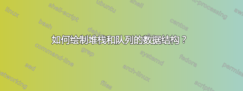
我需要绘制一个堆栈数据结构来在第一个概念课程中解释它以及队列。
\begin{tikzpicture}[draw, minimum width=1cm, minimum height=0.5cm]
\node[draw] (in) at (-1,2) {};
\node[draw] (out) at (1,-2) {};
\matrix (queue)[matrix of nodes, nodes={draw, nodes={draw}}, nodes in empty cells] { \\ \\ \\ \\ };
\draw[-latex] (0.25,-1) .. controls (0.25,-1.25) and (1,-1.25) .. (out.north);
\draw[-latex] (in.south) .. controls (-1, 1.5) and (-0.25,1.5) .. (-0.25,1);
\end{tikzpicture}
答案1
给你一个开始(无论如何我现在有空闲时间:))
\documentclass[tikz,margin=1]{standalone}
\usetikzlibrary{arrows.meta}
\tikzset{
    queue element/.style={
        draw,very thin,rounded corners,
        fill=yellow!30,
        minimum width=1cm,minimum height=.5cm,
        font=\sffamily\footnotesize
    },
    >={[scale=0.8]Triangle}
}
\begin{document}
\begin{tikzpicture}
\fill[green!20] (5.1,.35) rectangle (-.6,-.35);
\draw[green,thick,>->] (-.6,.35) -- (5.1,.35);
\draw[green,thick,>->] (-.6,-.35) -- (5.1,-.35);
\foreach \i/\name in {1/C,2/B,3/A}
    \node[queue element] (\name) at (1.5*\i,0) {\name};
\draw[<-] ([yshift=.2cm]A.north) -- ++ (0,.5) node[above] {front};
\draw[<-] ([yshift=.2cm]C.north) -- ++ (0,.5) node[above] {rear};
\path (6,0) node[right] {before};
\node[queue element] (D) at (-2,1) {D};
\draw[->,very thick] (D.south) to[out=-90,in=180] (-.7,0);

\scope[yshift=-3cm] % queue after
\fill[green!20] (5.1,.35) rectangle (-.6,-.35);
\draw[green,thick,>->] (-.6,.35) -- (5.1,.35);
\draw[green,thick,>->] (-.6,-.35) -- (5.1,-.35);
\foreach \i/\name in {0/D,1/C,2/B,3/A}
    \node[queue element] (\name) at (1.5*\i,0) {\name};
\draw[<-] ([yshift=.2cm]A.north) -- ++ (0,.5) node[above] {front};
\draw[<-] ([yshift=.2cm]D.north) -- ++ (0,.5) node[above] {rear};
\path (6,0) node[right] {after};
\endscope
\end{tikzpicture}
\end{document}

稍加修改,您就可以dequeue()得到enqueue()。
\documentclass[tikz,margin=1]{standalone}
\usetikzlibrary{arrows.meta}
\tikzset{
    queue element/.style={
        draw,very thin,rounded corners,
        fill=yellow!30,
        minimum width=1cm,minimum height=.5cm,
        font=\sffamily\footnotesize
    },
    >={[scale=0.8]Triangle}
}
\begin{document}
\begin{tikzpicture}
\fill[green!20] (5.1,.35) rectangle (-.6,-.35);
\draw[green,thick,>->] (-.6,.35) -- (5.1,.35);
\draw[green,thick,>->] (-.6,-.35) -- (5.1,-.35);
\foreach \i/\name in {0/D,1/C,2/B,3/A}
    \node[queue element] (\name) at (1.5*\i,0) {\name};
\draw[<-] ([yshift=.2cm]A.north) -- ++ (0,.5) node[above] {front};
\draw[<-] ([yshift=.2cm]D.north) -- ++ (0,.5) node[above] {rear};
\draw[->,very thick] (5.2,0) to[out=0,in=90] ++ (1,-1);
\path (6,0) node[right] {before};

\scope[yshift=-3cm] % queue after
\fill[green!20] (5.1,.35) rectangle (-.6,-.35);
\draw[green,thick,>->] (-.6,.35) -- (5.1,.35);
\draw[green,thick,>->] (-.6,-.35) -- (5.1,-.35);
\foreach \i/\name in {0/D,1/C,2/B}
    \node[queue element] (\name) at (1.5*\i,0) {\name};
\draw[<-] ([yshift=.2cm]B.north) -- ++ (0,.5) node[above] {front};
\draw[<-] ([yshift=.2cm]D.north) -- ++ (0,.5) node[above] {rear};
\path (6,0) node[right] {after};
\endscope
\end{tikzpicture}
\end{document}

使用同样的技术,你也可以说明stack数据结构:)
\documentclass[tikz,margin=1]{standalone}
\usetikzlibrary{arrows.meta}
\tikzset{
    queue element/.style={
        draw,very thin,rounded corners,
        fill=yellow!30,
        minimum width=1cm,minimum height=.5cm,
        font=\sffamily\footnotesize
    },
    >={[scale=0.8]Triangle}
}
\begin{document}
\begin{tikzpicture}
\fill[green!20] (5.1,.35) rectangle (-.6,-.35);
\draw[green,thick] (-.6,.35) -- (5.1,.35) |- (-.6,-.35);
\foreach \i/\name in {1/C,2/B,3/A}
    \node[queue element] (\name) at (1.5*\i,0) {\name};
\draw[<-] ([yshift=.2cm]A.north) -- ++ (0,.5) node[above] {rear};
\draw[<-] ([yshift=.2cm]C.north) -- ++ (0,.5) node[above] {front};
\path (6,0) node[right] {before};
\node[queue element] (D) at (-2,1) {D};
\draw[->,very thick] (D.south) to[out=-90,in=180] (-.7,0);

\scope[yshift=-3cm] % stack after
\fill[green!20] (5.1,.35) rectangle (-.6,-.35);
\draw[green,thick] (-.6,.35) -- (5.1,.35) |- (-.6,-.35);
\foreach \i/\name in {0/D,1/C,2/B,3/A}
    \node[queue element] (\name) at (1.5*\i,0) {\name};
\draw[<-] ([yshift=.2cm]A.north) -- ++ (0,.5) node[above] {rear};
\draw[<-] ([yshift=.2cm]D.north) -- ++ (0,.5) node[above] {front};
\path (6,0) node[right] {after};
\endscope
\end{tikzpicture}
\end{document}

\documentclass[tikz,margin=1]{standalone}
\usetikzlibrary{arrows.meta}
\tikzset{
    queue element/.style={
        draw,very thin,rounded corners,
        fill=yellow!30,
        minimum width=1cm,minimum height=.5cm,
        font=\sffamily\footnotesize
    },
    >={[scale=0.8]Triangle}
}
\begin{document}
\begin{tikzpicture}
\fill[green!20] (5.1,.35) rectangle (-.6,-.35);
\draw[green,thick] (-.6,.35) -- (5.1,.35) |- (-.6,-.35);
\foreach \i/\name in {0/D,1/C,2/B,3/A}
    \node[queue element] (\name) at (1.5*\i,0) {\name};
\draw[<-] ([yshift=.2cm]A.north) -- ++ (0,.5) node[above] {rear};
\draw[<-] ([yshift=.2cm]D.north) -- ++ (0,.5) node[above] {front};
\draw[->,very thick] (-.7,0) to[out=180,in=90] ++ (-1,-1);
\path (6,0) node[right] {before};

\scope[yshift=-3cm] % stack after
\fill[green!20] (5.1,.35) rectangle (-.6,-.35);
\draw[green,thick] (-.6,.35) -- (5.1,.35) |- (-.6,-.35);
\foreach \i/\name in {1/C,2/B,3/A}
    \node[queue element] (\name) at (1.5*\i,0) {\name};
\draw[<-] ([yshift=.2cm]A.north) -- ++ (0,.5) node[above] {rear};
\draw[<-] ([yshift=.2cm]C.north) -- ++ (0,.5) node[above] {front};
\path (6,0) node[right] {after};
\endscope
\end{tikzpicture}
\end{document}

答案2
稍微变化一下焦耳伏特解决方案。
我使用 来matrix of nodes声明 ,queue它也可以用于水平或垂直堆栈。matrix节点可以用作 ,background area并且不需要外部矩形。
内部节点被方便地标记为和front,rear以避免使用特定名称。
\documentclass[tikz,margin=2mm]{standalone}
\usetikzlibrary{arrows.meta, matrix, positioning}
\tikzset{
    queue element/.style={
        draw,very thin,rounded corners,
        fill=yellow!30,
        minimum width=1cm,minimum height=.5cm,
        font=\sffamily\footnotesize
    },
    >={[scale=0.8]Triangle},
    queue/.style={matrix of nodes,
        nodes in empty cells,
        nodes={queue element, anchor=center},
        fill=green!20,
        column sep=5mm,
        row sep=2mm,
    },
}
\begin{document}
\begin{tikzpicture}

\matrix[queue] (Q1) {
|(rear)| D & C & B &|(front)| A\\};
\draw[green,thick,>->] (Q1.north west) -- (Q1.north east);
\draw[green,thick,>->] (Q1.south west) -- (Q1.south east);
\draw[<-] ([yshift=.2cm]front.north) -- ++ (0,.5) node[above] {front};
\draw[<-] ([yshift=.2cm]rear.north) -- ++ (0,.5) node[above] {rear};
\draw[->,very thick] (Q1.east) to[out=0,in=90] node[pos=.6, above right] (aux) {before} ++ (1,-1);

\scope[yshift=-2cm] % queue after
\matrix[queue] (Q1) {
|(rear)| D & C &|(front)| B &|[fill=none, draw=none]| \\};
\draw[green,thick,>->] (Q1.north west) -- (Q1.north east);
\draw[green,thick,>->] (Q1.south west) -- (Q1.south east);
\draw[<-] ([yshift=.2cm]front.north) -- ++ (0,.5) node[above] {front};
\draw[<-] ([yshift=.2cm]rear.north) -- ++ (0,.5) node[above] {rear};
\node at (aux|-Q1) {after};
\endscope
\end{tikzpicture}

\begin{tikzpicture}

\matrix[queue] (Q1) {
|[fill=none, draw=none]| \\
|(front)| C\\
B\\
|(rear)| A\\};
\draw[green,thick,-] (Q1.north west) |-(Q1.south)-| (Q1.north east);
\draw[<-] ([xshift=.2cm]front.east) -- ++ (0:.5) node[right] {front};
\draw[<-] ([xshift=.2cm]rear.east) -- ++ (0:.5) node[right] {rear};
\draw[<-,very thick] (Q1.north) to[out=90,in=190] ++ (1,1) node[right, queue element] (D) {D};
\node[below=3mm of Q1.south east] {before};

\scope[xshift=3.5cm] % queue after
\matrix[queue] (Q1) {
|(front)| D \\
 C\\
B\\
|(rear)| A\\};
\draw[green,thick,-] (Q1.north west) |-(Q1.south)-| (Q1.north east);
\draw[<-] ([xshift=.2cm]front.east) -- ++ (0:.5) node[right] {front};
\draw[<-] ([xshift=.2cm]rear.east) -- ++ (0:.5) node[right] {rear};
\node[below=3mm of Q1.south east] {after};
\endscope
\end{tikzpicture}
\end{document}

答案3
\documentclass[tikz,border=3.14mm]{standalone}
\usetikzlibrary{backgrounds,fit,chains}
\begin{document}
\begin{tikzpicture}[lazy/.style={rounded corners,fill=gray!30,draw=gray!50,
minimum width=3em,minimum height=4ex},arr/.style={very thick,-stealth},
arr2/.style={very thick,stealth-},font=\sffamily]
 \begin{scope}[start chain=going left,node distance=1em,nodes={lazy,on chain}]
  \node[lazy] (A2){A};
  \node[lazy] (B2){B};
  \node[lazy] (C2){C};
  \node[lazy] (D2){D};
 \end{scope}
 \begin{scope}[on background layer]
 \node[fit=(A2) (D2),top color=gray!20,bottom color=gray!10,inner sep=1em](F2){};
 \end{scope}
 \foreach \X in {north,south}
 {\draw[arr,gray!50]  (F2.\X\space west) -- (F2.\X\space east);}
 \begin{scope}[yshift=3cm,start chain=going left,node distance=1em,nodes={lazy,on chain}]
  \node[lazy] (A1){A};
  \node[lazy] (B1){B};
  \node[lazy] (C1){C};
 \end{scope}
 \begin{scope}[on background layer]
  \node[fit=(A1) (D2.west|-A1),top color=gray!20,bottom color=gray!10,inner sep=1em](F1){};
 \end{scope}
 \foreach \X in {north,south}
 {\draw[arr,gray!50]  (F1.\X\space west) -- (F1.\X\space east);}
 \node[left=2em of F1.north west,lazy] (D1) {D};
 \draw[arr,black] (D1.south) to[out=-60,in=180] (F1);
 \draw[arr2] (A2|-F2.north) -- ++ (0,1em) node[above]{Front};
 \draw[arr2] (D2|-F2.north) -- ++ (0,1em) node[above]{Rear};
 \draw[arr2] (A1|-F1.north) -- ++ (0,1em) node[above]{Front};
 \draw[arr2] (C1|-F1.north) -- ++ (0,1em) node[above]{Rear};
\end{tikzpicture}
\end{document}
