

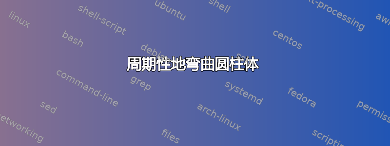
我必须实现一个由类似圆柱形的元素组成的数组。但是,下面的代码只能提供一个直圆柱体(代码来源:此链接),而是需要像图中所示那样弯曲它,可能不是那个角度而是垂直的。但我似乎无法成功。我甚至无法将气缸数从一个增加到更多。
\documentclass[border=2mm]{standalone}
\usepackage{xcolor}
\definecolor{mycolor}{RGB}{8,108,131}
\usepackage{tikz}
\usetikzlibrary{positioning}
\usetikzlibrary{backgrounds}
\usetikzlibrary{shapes.geometric}
\usetikzlibrary{calc}
\tikzset{cylinder end fill/.style={path picture={
            \pgftransformshift{\centerpoint}%
            \pgftransformrotate{\rotate}%
            \pgfpathmoveto{\beforetop}%
            \pgfpatharc{90}{-270}{\xradius and \yradius}%
            \pgfpathclose
            \pgfsetfillcolor{#1}%
            \pgfusepath{fill}}
}}
\begin{document}
    \begin{tikzpicture}
    \begin{scope}[on background layer]
    \path let \p1=(0.2,8.4),
    \n1={atan2(\y1,\x1)},\n2={veclen(\y1,\x1)} in
    node[cylinder, rotate=270,
    minimum height=0.85*\n2,minimum width=1cm,aspect=1.0,
    cylinder end fill=red,
    left color=red!30,right color=black,middle color=red!80, opacity=0.7,
    draw] at (0.8,4.7) {1};
    \end{scope}
    \end{tikzpicture}
\end{document}

答案1
以下是一个答案,它产生了类似这样的内容。关键要素是图书馆perspective。它利用了一个Symbol 1 的绝妙技巧(和往常一样,真正酷的东西并没有太多的投票...... ;-) 这使我们能够避免编写tpp cs:x=...,y=...,z=...,我们只需协调并切换switch on perspective。由于装饰会导致dimension too large错误,颜色渐变和线宽变化是通过循环实现的,这就是为什么这需要一些时间来编译(在 5 年前的 MacBook Pro 上需要 12 秒)。下面可以找到一个更快的、基于装饰的答案,适用于不太弯曲的路径。
\documentclass[tikz,border=3mm]{standalone}
\usetikzlibrary{calc,perspective,3d}
\makeatletter
\tikzset{switch on perspective/.code={\def\tikz@parse@splitxyz##1##2##3,##4,{%
    \def\pgfutil@next{\tikz@scan@one@point##1(tpp cs:x={##2},y={##3},z={##4})}% https://tex.stackexchange.com/a/365418/194703
}}}
\makeatother

\begin{document}
\begin{tikzpicture}[3d view={-70}{15}]
 \begin{scope}[perspective={p = {(20,0,0)}, q = {(0,20,0)}},switch on perspective]
  \path let \p1=($(0,2,0)-(0,0,0)$),\p2=($(20,2,0)-(20,0,0)$),
     \n1={atan2(\y1,\x1)/2+atan2(\y2,\x2)/2} in
   [left color=black,right color=gray!80!black,shading angle=\n1]
    (0,-3,0) -- (0,3,0) -- (20,3,0) -- (20,-3,0) -- cycle;
  \begin{scope}
   \clip (1,-3,0) -- (1,3,0) -- (20,3,0) -- (20,-3,0) -- cycle;
   \foreach \X [count=\Y] in {2,1.2,-1.2,-2}
   {\foreach \Z [evaluate=\Z as \CF using {int(90-\Z/3)}] in {1,...,95}
   {\draw let
    \p1=($(0.8+\Z/5,\X+0.5,0)-(0.8+\Z/5,\X-0.5,0)$),
    \n1={sqrt(\x1*\x1+\y1*\y1)} in [line width=0.1*\n1,gray!\CF!black]
    plot[variable=\t,domain=0.8+\Z/5:0.8+\Z/5+0.4,samples=5,smooth]
    (\t,{\X+0.2*pow(-1,\Y+1)*isodd(int(\t/2.05))},0) ;}}
  \path foreach \X [count=\Y] in {2,1.2,-1.2,-2}
   {(1,{\X+pow(-1,\Y+1)*0.2*isodd(int(1/2.05))},0) coordinate (aux\Y) };
  \end{scope}
 \end{scope}
 \begin{scope}[canvas is xz plane at y=0]
  \fill[rotate=-15] foreach \X in {1,...,4} {(aux\X) circle[x radius=5pt,y radius=1pt]};
 \end{scope}
\end{tikzpicture}
\end{document}

对于直圆柱体来说没有问题,装饰得很好。
\documentclass[tikz,border=3mm]{standalone}
\usetikzlibrary{calc,decorations,perspective,3d}
\makeatletter
\tikzset{switch on perspective/.code={\def\tikz@parse@splitxyz##1##2##3,##4,{%
    \def\pgfutil@next{\tikz@scan@one@point##1(tpp cs:x={##2},y={##3},z={##4})}% https://tex.stackexchange.com/a/365418/194703
}}}
\makeatother
% the following decoration is based on
% https://tex.stackexchange.com/a/14295/128068 and
% https://tex.stackexchange.com/a/471222
\pgfkeys{/pgf/decoration/.cd,
         start color/.store in=\startcolor,
         start color=black,
         end color/.store in=\endcolor,
         end color=black,
         varying line width steps/.initial=100
}
\pgfdeclaredecoration{width and color change}{initial}{
 \state{initial}[width=0pt, next state=line, persistent precomputation={%
   \pgfmathparse{\pgfdecoratedpathlength/\pgfkeysvalueof{/pgf/decoration/varying line width steps}}%
   \let\increment=\pgfmathresult%
   \def\x{0}%
 }]{}
 \state{line}[width=\increment pt,   persistent postcomputation={%
   \pgfmathsetmacro{\x}{\x+\increment}
   },next state=line]{%
   \pgfmathparse{varyinglw(100*(\x/\pgfdecoratedpathlength))}
   \pgfsetlinewidth{\pgfmathresult pt}%
   \pgfpathmoveto{\pgfpointorigin}%
   \pgfmathsetmacro{\steplength}{1.4*\increment}
   \pgfpathlineto{\pgfqpoint{\steplength pt}{0pt}}%
   \pgfmathsetmacro{\y}{100*(\x/\pgfdecoratedpathlength)}
   \pgfsetstrokecolor{\endcolor!\y!\startcolor}%
   \pgfusepath{stroke}%
 }
 \state{final}{%
   \pgfsetlinewidth{\pgflinewidth}%
   \pgfpathmoveto{\pgfpointorigin}%
   \pgfmathsetmacro{\y}{100*(\x/\pgfdecoratedpathlength)}
   \color{\endcolor!\y!\startcolor}%
   \pgfusepath{stroke}%
 }
}


\begin{document}
\begin{tikzpicture}[3d view={-70}{15}]
 \begin{scope}[perspective={p = {(20,0,0)}, q = {(0,20,0)}},switch on perspective]
  \path let \p1=($(0,2,0)-(0,0,0)$),\p2=($(20,2,0)-(20,0,0)$),
     \n1={atan2(\y1,\x1)/2+atan2(\y2,\x2)/2} in
   [left color=black,right color=gray!80!black,shading angle=\n1]
    (0,-3,0) -- (0,3,0) -- (20,3,0) -- (20,-3,0) -- cycle;
  \begin{scope}
   \clip (1,-3,0) -- (1,3,0) -- (20,3,0) -- (20,-3,0) -- cycle;
   \foreach \X [count=\Y] in {2,1.2,-1.2,-2}
   {\draw[decorate,decoration={width and color change}] let
    \p1=($(10,\X+0.5,0)-(10,\X-0.5,0)$),\p2=($(1,\X+0.5,0)-(1,\X-0.5,0)$),
    \n1={sqrt(\x1*\x1+\y1*\y1)},\n2={sqrt(\x2*\x2+\y2*\y2)} in
    [declare function={varyinglw(\x)=0.1*\n1+0.1*(\n2-\n1)*\x/100;},
    /pgf/decoration/start color=gray!70!black,/pgf/decoration/end color=gray]
   (20,\X,0) -- (1,\X,0) coordinate (aux\Y);}
  \end{scope}
 \end{scope}
 \begin{scope}[canvas is xz plane at y=0]
  \fill[rotate=-15] foreach \X in {1,...,4} {(aux\X) circle[x radius=5pt,y radius=1pt]};
 \end{scope}
\end{tikzpicture}
\end{document}

也许人们也可以找到曲线路径起作用的参数区域,但最好花时间尝试教授这些装饰fpu。