

我遇到了这个非常有用的代码,但是,当我运行代码时,所有节点都出现了错误(例如没有形状被命名A-2-1),我不知道问题出在哪里,因为节点的标记方式与其他代码配合得很好。有人知道这里的问题是什么吗?
% Author : Alain Matthes
% Source : http://altermundus.com/pages/examples.html
\documentclass[]{article}

\usepackage[utf8]{inputenc}
\usepackage[upright]{fourier}
\usepackage{tikz}
\usetikzlibrary{matrix,arrows,decorations.pathmorphing}
\begin{document}

% l' unite
\newcommand{\myunit}{1 cm}
\tikzset{
    node style sp/.style={draw,circle,minimum size=\myunit},
    node style ge/.style={circle,minimum size=\myunit},
    arrow style mul/.style={draw,sloped,midway,fill=white},
    arrow style plus/.style={midway,sloped,fill=white},
}

\begin{tikzpicture}[>=latex]
% les matrices
\matrix(A)[matrix of math nodes,%
             nodes = {node style ge},%
             left delimiter  = (,%
             right delimiter = )] at (0,0)
{%
  a_{11} & a_{12} & \ldots & a_{1p}  \\
  \node[node style sp] {a_{21}};%
         & \node[node style sp] {a_{22}};%
                  & \ldots%
                           & \node[node style sp] {a_{2p}}; \\
  \vdots & \vdots & \ddots & \vdots  \\
  a_{n1} & a_{n2} & \ldots & a_{np}  \\
};
\node [draw,below=10pt] at (A.south)
    { $A$ : \textcolor{red}{$n$ rows} $p$ columns};

\matrix (B) [matrix of math nodes,%
             nodes = {node style ge},%
             left delimiter  = (,%
             right delimiter =)] at (6*\myunit,6*\myunit)
{%
  b_{11} & \node[node style sp] {b_{12}};%
                  & \ldots & b_{1q}  \\
  b_{21} & \node[node style sp] {b_{22}};%
                  & \ldots & b_{2q}  \\
  \vdots & \vdots & \ddots & \vdots  \\
  b_{p1} & \node[node style sp] {b_{p2}};%
                  & \ldots & b_{pq}  \\
};
\node [draw,above=10pt] at (B.north)
    { $B$ : $p$ rows \textcolor{red}{$q$ columns}};
% matrice résultat
\matrix (C) [matrix of math nodes,%
             nodes = {node style ge},%
             left delimiter  = (,%
             right delimiter = )] at (6*\myunit,0)
{%
  c_{11} & c_{12} & \ldots & c_{1q} \\
  c_{21} & \node[node style sp,red] {c_{22}};%
                  & \ldots & c_{2q} \\
  \vdots & \vdots & \ddots & \vdots \\
  c_{n1} & c_{n2} & \ldots & c_{nq} \\
};
% les fleches
\draw[blue] (A-2-1.north) -- (C-2-2.north);
\draw[blue] (A-2-1.south) -- (C-2-2.south);
\draw[blue] (B-1-2.west)  -- (C-2-2.west);
\draw[blue] (B-1-2.east)  -- (C-2-2.east);
\draw[<->,red](A-2-1) to[in=180,out=90]
    node[arrow style mul] (x) {$a_{21}\times b_{12}$} (B-1-2);
\draw[<->,red](A-2-2) to[in=180,out=90]
    node[arrow style mul] (y) {$a_{22}\times b_{22}$} (B-2-2);
\draw[<->,red](A-2-4) to[in=180,out=90]
    node[arrow style mul] (z) {$a_{2p}\times b_{p2}$} (B-4-2);
\draw[red,->] (x) to node[arrow style plus] {$+$} (y)%
                  to node[arrow style plus] {$+\raisebox{.5ex}{\ldots}+$} (z)%
                  to (C-2-2.north west);


\node [draw,below=10pt] at (C.south)
    {$ C=A\times B$ : \textcolor{red}{$n$ rows}  \textcolor{red}{$q$ columns}};

\end{tikzpicture}

\begin{tikzpicture}[>=latex]
% unit
% defintion of matrices
\matrix (A) [matrix of math nodes,%
             nodes = {node style ge},%
             left delimiter  = (,%
             right delimiter = )] at (0,0)
{%
  a_{11} &\ldots & a_{1k} & \ldots & a_{1p}  \\
    \vdots & \ddots & \vdots & \vdots & \vdots \\
  \node[node style sp] {a_{i1}};& \ldots%
         & \node[node style sp] {a_{ik}};%
                  & \ldots%
                           & \node[node style sp] {a_{ip}}; \\
  \vdots & \vdots& \vdots & \ddots & \vdots  \\
  a_{n1}& \ldots & a_{nk} & \ldots & a_{np}  \\
};
\node [draw,below] at (A.south) { $A$ : \textcolor{red}{$n$ rows} $p$ columns};
\matrix (B) [matrix of math nodes,%
             nodes = {node style ge},%
             left delimiter  = (,%
             right delimiter =)] at (7*\myunit,7*\myunit)
{%
  b_{11} &  \ldots& \node[node style sp] {b_{1j}};%
                  & \ldots & b_{1q}  \\
  \vdots& \ddots & \vdots & \vdots & \vdots \\
  b_{k1} &  \ldots& \node[node style sp] {b_{kj}};%
                  & \ldots & b_{kq}  \\
  \vdots& \vdots & \vdots & \ddots & \vdots \\
  b_{p1} &  \ldots& \node[node style sp] {b_{pj}};%
                  & \ldots & b_{pq}  \\
};
\node [draw,above] at (B.north) { $B$ : $p$ rows \textcolor{red}{$q$ columns}};
% matrice resultat
\matrix (C) [matrix of math nodes,%
             nodes = {node style ge},%
             left delimiter  = (,%
             right delimiter = )] at (7*\myunit,0)
{%
  c_{11} & \ldots& c_{1j} & \ldots & c_{1q} \\
  \vdots& \ddots & \vdots & \vdots & \vdots \\
    c_{i1}& \ldots & \node[node style sp,red] {c_{ij}};%
                  & \ldots & c_{iq} \\
  \vdots& \vdots & \vdots & \ddots & \vdots \\
  c_{n1}& \ldots & c_{nk} & \ldots & c_{nq} \\
};
\node [draw,below] at (C.south)
    {$ C=A\times B$ : \textcolor{red}{$n$ rows}  \textcolor{red}{$q$ columns}};
% arrows
\draw[blue] (A-3-1.north) -- (C-3-3.north);
\draw[blue] (A-3-1.south) -- (C-3-3.south);
\draw[blue] (B-1-3.west)  -- (C-3-3.west);
\draw[blue] (B-1-3.east)  -- (C-3-3.east);
\draw[<->,red](A-3-1) to[in=180,out=90]
    node[arrow style mul] (x) {$a_{i1}\times b_{1j}$} (B-1-3);
\draw[<->,red](A-3-3) to[in=180,out=90]
    node[arrow style mul] (y) {$a_{ik}\times b_{kj}$}(B-3-3);
\draw[<->,red](A-3-5) to[in=180,out=90]
    node[arrow style mul] (z) {$a_{ip}\times b_{pj}$}(B-5-3);
\draw[red,->] (x) to node[arrow style plus] {$+\raisebox{.5ex}{\ldots}+$} (y)%
                  to node[arrow style plus] {$+\raisebox{.5ex}{\ldots}+$} (z);
                  %
                  % to (C-3-3.north west);
\draw[->,red,decorate,decoration=zigzag] (z) -- (C-3-3.north west);
\end{tikzpicture}
\end{document}
答案1
改为\node[node style sp] {a_{21}};写|[node style sp]| {a_{21}}:
\documentclass[]{article}

\usepackage[utf8]{inputenc}
\usepackage[upright]{fourier}
\usepackage{tikz}
\usetikzlibrary{arrows,matrix,decorations.pathmorphing}
\begin{document}

% l' unite
\newcommand{\myunit}{1 cm}
\tikzset{
    node style sp/.style={draw,circle,minimum size=\myunit},
    node style ge/.style={circle,minimum size=\myunit},
    arrow style mul/.style={draw,sloped,midway,fill=white},
    arrow style plus/.style={midway,sloped,fill=white},
}

\begin{tikzpicture}[>=latex]
% les matrices
\matrix (A) [matrix of math nodes,%
             nodes = {node style ge},%
             left delimiter  = (,%
             right delimiter = )]
{%
  a_{11} & a_{12} & \ldots & a_{1p}  \\
  |[node style sp]| {a_{21}}%
         & |[node style sp]| {a_{22}}%
                  & \ldots%
                           & |[node style sp]| {a_{2p}} \\
  \vdots & \vdots & \ddots & \vdots  \\
  a_{n1} & a_{n2} & \ldots & a_{np}  \\
};
\node [draw,below=10pt] at (A.south)
    { $A$ : \textcolor{red}{$n$ rows} $p$ columns};

\matrix (B) [matrix of math nodes,%
             nodes = {node style ge},%
             left delimiter  = (,%
             right delimiter =)] at (6*\myunit,6*\myunit)
{%
  b_{11} & |[node style sp]| {b_{12}}%
                  & \ldots & b_{1q}  \\
  b_{21} & |[node style sp]| {b_{22}}%
                  & \ldots & b_{2q}  \\
  \vdots & \vdots & \ddots & \vdots  \\
  b_{p1} & |[node style sp]| {b_{p2}}%
                  & \ldots & b_{pq}  \\
};
\node [draw,above=10pt] at (B.north)
    { $B$ : $p$ rows \textcolor{red}{$q$ columns}};
% matrice resultat
\matrix (C) [matrix of math nodes,%
             nodes = {node style ge},%
             left delimiter  = (,%
             right delimiter = )] at (6*\myunit,0)
{%
  c_{11} & c_{12} & \ldots & c_{1q} \\
  c_{21} & |[node style sp,red]| {c_{22}}%
                  & \ldots & c_{2q} \\
  \vdots & \vdots & \ddots & \vdots \\
  c_{n1} & c_{n2} & \ldots & c_{nq} \\
};
% les fleches
\draw[blue] (A-2-1.north) -- (C-2-2.north);
\draw[blue] (A-2-1.south) -- (C-2-2.south);
\draw[blue] (B-1-2.west)  -- (C-2-2.west);
\draw[blue] (B-1-2.east)  -- (C-2-2.east);
\draw[<->,red](A-2-1) to[in=180,out=90]
    node[arrow style mul] (x) {$a_{21}\times b_{12}$} (B-1-2);
\draw[<->,red](A-2-2) to[in=180,out=90]
    node[arrow style mul] (y) {$a_{22}\times b_{22}$} (B-2-2);
\draw[<->,red](A-2-4) to[in=180,out=90]
    node[arrow style mul] (z) {$a_{2p}\times b_{p2}$} (B-4-2);
\draw[red,->] (x) to node[arrow style plus] {$+$} (y)%
                  to node[arrow style plus] {$+\raisebox{.5ex}{\ldots}+$} (z)%
                  to (C-2-2.north west);


\node [draw,below=10pt] at (C.south)
    {$ C=A\times B$ : \textcolor{red}{$n$ rows}  \textcolor{red}{$q$ columns}};
\end{tikzpicture}
\end{document}

答案2
该矩阵定义为一组已经具有
\matrix(A)[matrix of math nodes,%
因此下面的第二个命令将节点嵌套在第一个节点中,这是非法的
\node[node style sp] {a_{21}};%
因此如果您打算这样做,则需要使用另一个别名来调用第二个/嵌套节点,而不是使用用于主矩阵(A)的 A-2-1
我给第二个嵌套节点赋予了单独的名称 (A-2-1) - 类似地,对于矩阵 (C),位于 (C-2-2) 的第二个嵌套节点被赋予了单独的名称
现在,当您在这两个节点之间使用绘制命令时,不会出现任何错误
\draw[blue] (A-2-1.north) -- (C-2-2.north);
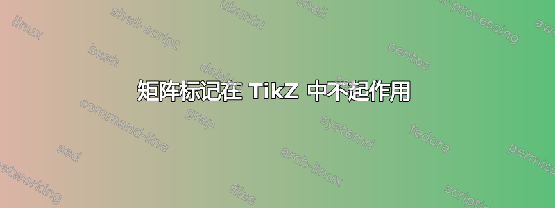
你会得到如下结果图

您还可以使用下面链接中描述的别名==