

问题后续:在 tikz 图形中向矢量添加标签
根据用户@js bibra 的回答,我得到了想要的结果
\documentclass[tikz,border=10pt]{standalone}
\usetikzlibrary{calc,patterns,angles,quotes}
\begin{document}
\begin{tikzpicture}
    % save length of g-vector and theta to macros
    \pgfmathsetmacro{\Gvec}{1.5}
    \pgfmathsetmacro{\myAngle}{30}
    % calculate lengths of vector components
    \pgfmathsetmacro{\Gcos}{\Gvec*cos(\myAngle)}
    \pgfmathsetmacro{\Gsin}{\Gvec*sin(\myAngle)}

    \coordinate (centro) at (0,0);
    \draw[dashed,gray,-] (centro) -- ++ (0,-3.5) node (mary) [black,below]{$ $};
    \draw[thick] (centro) -- ++(270+\myAngle:3) coordinate (bob);
    \pic [draw, ->, "$\theta$", angle eccentricity=1.5] {angle = mary--centro--bob};
    \draw [blue,-stealth] (bob) -- ($(bob)!\Gcos cm!(centro)$);
\draw [blue,-stealth] (bob) -- ($(bob)!\Gcos cm!(centro)$)node[right,pos=0.5, color=black](){$T$};
    \draw [-stealth] (bob) -- ($(bob)!-\Gcos cm!(centro)$)
      coordinate (gcos)
      node[midway,above right] {$a\cos\theta$};
    \draw [-stealth] (bob) -- ($(bob)!\Gsin cm!90:(centro)$)
      coordinate (gsin)
      node[midway,above left] {$a\sin\theta$};
    \draw [-stealth] (bob) -- ++(0,-\Gvec)
      coordinate (g)
      node[near end,left] {$g$};
    \pic [draw, ->, "$\theta$", angle eccentricity=1.5] {angle = g--bob--gcos};
    \filldraw [fill=black!40,draw=black] (bob) circle[radius=0.1];
\end{tikzpicture}
\end{document}
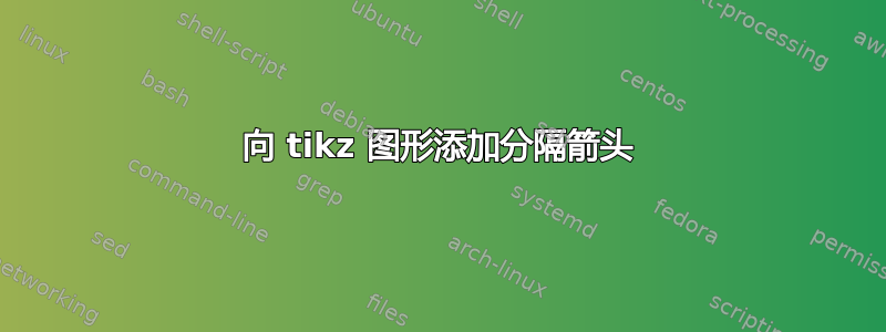
我想要知道的是包含两个箭头来界定字符串 L 的长度,如下图所示。 (忽略图片的其他细节)。再次感谢您的帮助!
答案1

\documentclass[tikz,border=10pt]{standalone}
\usetikzlibrary{calc,patterns,angles,quotes}
\usepackage{tkz-euclide}
\begin{document}
    \begin{tikzpicture}
        % save length of g-vector and theta to macros
        \pgfmathsetmacro{\Gvec}{1.5}
        \pgfmathsetmacro{\myAngle}{30}
        % calculate lengths of vector components
        \pgfmathsetmacro{\Gcos}{\Gvec*cos(\myAngle)}
        \pgfmathsetmacro{\Gsin}{\Gvec*sin(\myAngle)}

        \coordinate (centro) at (0,0);
        \draw[dashed,gray,-] (centro) -- ++ (0,-3.5) node (mary) [black,below]{$ $} ;

%       \tkzDrawSegment[dim={$g$,-20pt,above=0pt,font=\tiny}](centro,mary)
        \tkzDrawSegment[style=red, dashed, dim={$L$,-15pt,midway,font=\scriptsize, rotate=90}](centro,mary)
        \draw[thick] (centro) -- ++(270+\myAngle:3) coordinate (bob);
        \pic [draw, ->, "$\theta$", angle eccentricity=1.5] {angle = mary--centro--bob};
        \draw [blue,-stealth] (bob) -- ($(bob)!\Gcos cm!(centro)$)node[right,, color=black, font=\scriptsize](){$a$};
        \draw [-stealth] (bob) -- ($(bob)!-\Gcos cm!(centro)$)
        coordinate (gcos)
        node[midway,above right] {$a\cos\theta$};
        \draw [-stealth] (bob) -- ($(bob)!\Gsin cm!90:(centro)$)
        coordinate (gsin)
        node[midway,above left] {$a\sin\theta$};
        \draw [-stealth] (bob) -- ++(0,-\Gvec)
        coordinate (g)
        node[near end,left] {$g$};
        \pic [draw, ->, "$\theta$", angle eccentricity=1.5] {angle = g--bob--gcos};
        \filldraw [fill=black!40,draw=black] (bob) circle[radius=0.1];
    \end{tikzpicture}
\end{document}