

我有不同的光学设置,我想使用 来绘制pst-optexp,但不一定都在同一个文档中。例如,我有以下代码:
\documentclass[margin=5pt]{standalone}
\usepackage[dvipsnames,svgnames,pdf]{pstricks}
\usepackage{pdftricks}
\usepackage{auto-pst-pdf}
\usepackage{pst-optexp}
\usepackage{stackengine}
\begin{document}
    \begin{pspicture}(16,5)
        \psset[optexp]{fiber=none, usefiberstyle}
        \newpsstyle{Fiber}{linecolor=orange, linewidth=2\pslinewidth}
        %%Simple seed laser
        \pnodes(1, 1){DiodeIn} (2, 1){DiodeOut}
        \pnodes(3, 1) {FiberIn} (5, 1){FiberOut}
        \pnode(6, 1){SeedOutput}
        \pnodes(9, 4){TSFIn}(11, 4){TSFOut}
        \pnodes(13, 3){LoopIn}(13, 2){LoopOut}
        \pnodes(9, 1){OutputIsolatorIn}(11,1){OutputIsolatorOut}
        \pnodes(13, 2){OutputSplitter}(16, 3){LaserOutHigh}(16, 1){LaserOutLow}
        \optdiode[compname=SeedDiode, position=start](DiodeIn)(DiodeOut){\begin{tabular}{@{}c@{}}Laser\\diode\end{tabular}}
        \optfiber[compname=SeedFiber, addtoFiberOut={ncurv=1,angleB=0},addtoFiberIn={ncurv=1,angleA=0},compshift=-1,label=-1.5.l] (FiberIn)(FiberOut){\begin{tabular}
                {@{}c@{}}
                Active\\Fiber
            \end{tabular}}

        \nput{90}{SeedOutput}{Seed Output}

        \drawfiber{SeedDiode}{SeedFiber}
        \drawfiber[ArrowInside=->]{SeedFiber}(SeedOutput)

        %%Simple amplifier
        \pnodes(8, 1){AmpIn}
        \pnodes(11, 1){ActiveFiberIn}(13, 1){ActiveFiberOut}
        \pnodes(8, 4){PumpDiodeIn}(9, 4){PumpDiodeOut}
        \pnode(14, 2){AmpOut}
        \optdiode[compname=AmpDiode, position=start](PumpDiodeIn)(PumpDiodeOut){\begin{tabular}{@{}c@{}}Laser\\diode\end{tabular}}
        \wdmcoupler[compname=SignalPumpCombiner, coupleralign=bottom, couplersize=0.35](PumpDiodeOut)(AmpIn)(ActiveFiberIn){\begin{tabular}{@{}c@{}}
                Pump\\Combiner
        \end{tabular}}
        \optfiber[compname=PumpFiber, addtoFiberOut={ncurv=1,angleB=0},addtoFiberIn={ncurv=1,angleA=0},compshift=-1,label=-1.5.l] (ActiveFiberIn)(ActiveFiberOut){Active fiber}

        \nput{-90}{AmpIn}{Amp Input}
        \nput{90}{AmpOut}{Amp Output}

        \drawfiber{AmpDiode}{SignalPumpCombiner}
        \drawfiber[ArrowInside=->](AmpIn){SignalPumpCombiner}
        \drawfiber{SignalPumpCombiner}{PumpFiber}
        \drawfiber[ArrowInside=->, arrows=->]{PumpFiber}(AmpOut)

        %Connect both setups
        \drawfiber[linecolor=green](SeedOutput)(AmpIn)
    \end{pspicture}
\end{document}
这让我
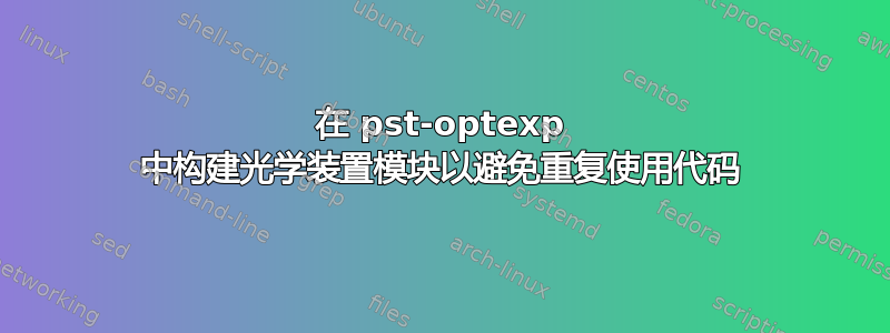
 如果我只想显示绿色光纤左侧的部分,我必须注释掉负责右侧的代码,如果我只想显示右侧,我必须注释掉左侧的代码,并将剩余的所有内容移到左侧(否则我会有很多空白)。
因此,为了让一切变得更简单,我考虑将每个块放在自己的文件/“函数”中,这样我就可以编写类似于
\documentclass[margin=5pt]{standalone}
\usepackage[dvipsnames,svgnames,pdf]{pstricks}
\usepackage{pdftricks}
\usepackage{auto-pst-pdf}
\usepackage{pst-optexp}
\usepackage{stackengine}
%%Somehow include seed/amp pst files here
\begin{document}
    \begin{pspicture}(16,5)
        \drawpart(%Coordinates here
        ){Seed}
        \drawpart(%Coordinates here
        ){Amp}

        %Connect both setups
        \drawfiber[linecolor=green](Seed)(Amp)
    \end{pspicture}
\end{document}
这有可能吗?或者还有其他方法可以实现我的目标(即在重用块时简化我的代码)吗?
答案1
您可以使用 定义一个简单的命令\def,该命令将组件的坐标和用于连接不同组件的相应输入/输出节点的名称作为输入参数。然后使用 PSTricks 完成定位\rput。
当然,你可以将组件定义移动到其他文件并将其包含在\input{mycomponents}
\documentclass[margin=5pt]{standalone}
\usepackage[dvipsnames,svgnames,pdf]{pstricks}
\usepackage{pdftricks}
\usepackage{auto-pst-pdf}
\usepackage{pst-optexp}
\usepackage{stackengine}
% Simple seed laser
%
% #1 is the coordinate where to position the component
% #2 is the name of the output node
\def\SimpleSeedLaser(#1)#2{%
  \rput(#1){%
    \def\SeedOutput{#2}%
    \pnodes(1, 1){DiodeIn}
    \pnode(6, 1){\SeedOutput}
    \optdiode[compname=SeedDiode, position=start](DiodeIn)(\SeedOutput){%
      \begin{tabular}{@{}c@{}}Laser\\diode\end{tabular}}
    \optfiber[compname=SeedFiber,compshift=-1,label=-1.5.l, addtoFiberOut={ArrowInside=->}](DiodeIn)(\SeedOutput){%
      \begin{tabular}{@{}c@{}}Active\\Fiber\end{tabular}}
    \nput{90}{\SeedOutput}{Seed Output}
  }%
}%
% Simple amplifier
% #1 is the coordinate where to position the component
% #2 is the name of the input node
\def\SimpleAmplifier(#1)#2{%
  \rput(#1){%
    \def\AmpIn{#2}%
    \pnodes(0, 1){\AmpIn}
    \pnodes(3, 1){ActiveFiberIn}(5, 1){ActiveFiberOut}
    \pnodes(0, 4){PumpDiodeIn}(1, 4){PumpDiodeOut}
    \pnode(6, 2){AmpOut}
    \optdiode[compname=AmpDiode, position=start](PumpDiodeIn)(PumpDiodeOut){%
      \begin{tabular}{@{}c@{}}Laser\\diode\end{tabular}}
    \wdmcoupler[compname=SignalPumpCombiner, coupleralign=bottom, couplersize=0.35, fiber=i](PumpDiodeIn)(\AmpIn)(ActiveFiberIn){%
      \begin{tabular}{@{}c@{}}Pump\\Combiner\end{tabular}}
    \optfiber[compname=PumpFiber, compshift=-1,label=-1.5.l, fiber=i](\oenodeOut{SignalPumpCombiner})(ActiveFiberOut){Active fiber}

    \nput{-90}{\AmpIn}{Amp Input}
    \nput{90}{AmpOut}{Amp Output}

    \drawfiber[ArrowInside=->, arrows=->]{PumpFiber}(AmpOut)
  }%
}%
\begin{document}
    \begin{pspicture}(16,5)
        \newpsstyle{Fiber}{linecolor=orange, linewidth=2\pslinewidth}
        \SimpleSeedLaser(0,0){SeedOutput}

        %\psset[optexp]{fiber=none}
        \SimpleAmplifier(8,0){AmpIn}

        %Connect both setups
        \drawfiber[linecolor=green](SeedOutput)(AmpIn)
    \end{pspicture}
\end{document}

请注意,我对您的代码做了进一步的优化。
一般情况下,无需用 移除所有自动绘制的光纤
\psset{fiber=none}。种子激光器只需要两个节点,可用于所有组件。如果选择正确的节点,自动绘制的光纤就没问题。您还可以微调要拉的光纤。对于我使用的耦合器
fibers=i,它会拉两根输入光纤,但不拉输出光纤。仅当您将纤维与组件一起绘制时才使用
addtoFiber*。否则这些设置无效。如果需要,您可以使用各种
\oenode命令来访问组件节点,例如用于定位组件。我使用它来绘制具有自动输入光纤的活动光纤。因此,只有输出光纤必须明确绘制,因为相对于其余组件存在偏移。