

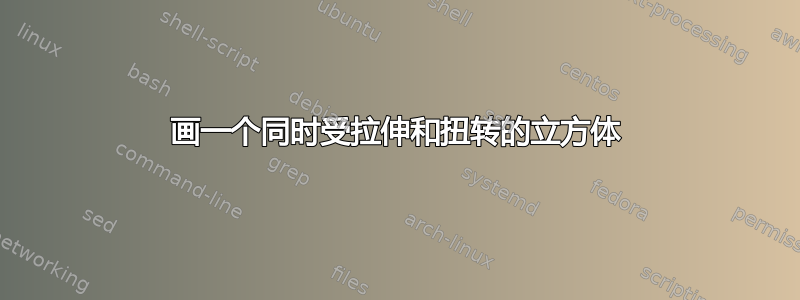
我想画一个同时受到拉伸和扭转的立方体,如下图所示:
我已经尝试了扩展部分(附加代码),但不知道如何将其与扭转部分结合起来。
\documentclass[tikz,border=0mm]{standalone}
\usetikzlibrary{3d, perspective, calc, bending}
%
\definecolor{myRed}{RGB}{180,80,80}
\definecolor{myGreen}{RGB}{55,175,85}
\begin{document}
    %%%%%%%%%%%%%%%%%%%%%%%%%%%%%%%%%%%%%%%%%%%%%%%%%%%%%%%%%%%%%%%%%%%%%%%%%%%%%%%%
    \begin{tikzpicture}[x=1cm, y=1cm, 3d view={65}{25}]
        %-------------------------------------------------------------------------------
        \def\h{1 * 5}
        \def\w{1 * 5}
        \def\d{1 * 5}
        \coordinate (a) at ( 0, 0, 0);
        \coordinate (b) at (\d, 0, 0);
        \coordinate (c) at (\d,\w, 0);
        \coordinate (d) at ( 0,\w, 0);
        \coordinate (e) at ( 0, 0,\h);
        \coordinate (f) at (\d, 0,\h);
        \coordinate (g) at (\d,\w,\h);
        \coordinate (h) at ( 0,\w,\h);
        \coordinate (m) at (\d/2,\w/2,\h);

        \tikzset{
            face/.style = {fill opacity=0.5},
            edge/.style = {draw, thin, line join=round},
            top/.style = {edge,face,fill=black!30},
            bottom/.style = {edge, face, fill=yellow!90},
            side/.style = {edge, face, fill=myGreen!40},
            label/.style = {fill=white, inner sep=0.5ex},
            rot/.style={ultra thick,-{latex[bend]}},
            fixedbot/.style = {edge, face, fill=black!50},
        };

        \draw[bottom,draw opacity=0.5] (a) -- (b) -- (c) -- (d) -- cycle;
        \draw[thick, dashed, orange] (a) node[below left]{$\mathbf{A}$} -- (g) node[above right]{$\mathbf{B}$};
        \draw[top]                     (e) -- (f) -- (g) -- (h) -- cycle;

        \draw[side,draw opacity=0.2]   (d) -- (a) -- (e) -- (h) -- cycle;
        \draw[side,draw opacity=0.2]   (c) -- (d) --(h) -- (g) -- cycle;
        \draw[side,fill opacity=0.5]   (a) -- (b) -- (f) -- (e) -- cycle;
        \draw[side,fill opacity=0.5]   (b) -- (c) -- (g) -- (f) -- cycle;

        %BCs labels
        \draw[draw=none] (e) -- (g) node[pos=0.8] {$\Omega_\mathsf{top}$};
        \draw[draw=none] (a) -- (c) node[pos=0.5] {$\Omega_\mathsf{bottom}$};

        %Coordinates
        \draw[thick,-latex] (a) -- (2,0,0) node[above] {$x$};
        \draw[thick,-latex] (a) -- (0,2,0) node[left=0.5ex] {$y$};
        \draw[thick,-latex] (a) -- (0,0,2) node[left]  {$z$};

        \begin{scope}[canvas is xy plane at z=0]
            \draw[help lines] (-1,-1) grid[step=5] (5.9,5.9);
            \draw[latex-latex] (a |- 45:-2) -- (b |- 45:-2) node[midway,label] {$b$};
        \end{scope}
        \begin{scope}[canvas is yx plane at z=0]
            \draw[latex-latex] (b |- 45:9) -- (c |- 45:9) node[midway,label] {$b$};
        \end{scope}
        \begin{scope}[canvas is zx plane at y=-1]
            \draw[latex-latex] (a |- 45:-1) -- (e |- 45:-1) node[midway,above,label] {$b$};
        \end{scope}

        %--------------------------------------------------------------------------------
        % Deformed cube
        \begin{scope}[canvas is yx plane at z=6.0]
            \coordinate (e1) at ( 0, 0,\h);
            \coordinate (f1) at (\d, 0,\h);
            \coordinate (g1) at (\d,\w,\h);
            \coordinate (h1) at ( 0,\w,\h);

            \draw[dash dot, top]                     (e1) -- (f1) -- (g1) -- (h1) -- cycle;
            \draw[dash dot]   (d) -- (a) -- (e1) -- (f1) -- cycle;
            \draw[dash dot]   (c) -- (d) -- (f1) -- (g1) -- cycle;
            \draw[dash dot]   (a) -- (b) -- (h1) -- (e1) -- cycle;
            \draw[dash dot]   (b) -- (c) -- (g1) -- (h1) -- cycle;

        \end{scope}
        %-------------------------------------------------------------------------------
        \begin{scope}[canvas is zx plane at y=-1]
            \draw[latex-latex] (e |- 45:-1) -- (e1 |- 45:-1)  node[midway,label] {$\lambda_z$};
        \end{scope}
        %--------------------------------------------------------------------------------

    \end{tikzpicture}
    %%%%%%%%%%%%%%%%%%%%%%%%%%%%%%%%%%%%%%%%%%%%%%%%%%%%%%%%%%%%%%%%%%%%%%%%%%%%%%%%
    %
\end{document}
答案1
这是一种简单的方法,绘制一个绘制扭曲边缘的 3d 函数。只需几个\foreach命令即可。
\documentclass[border=2mm]{standalone}
\usepackage    {tikz}
\usetikzlibrary{3d}

% colors
\definecolor{myRed}  {RGB}{180, 80, 80}
\definecolor{myGreen}{RGB}{ 55,175, 85}

\begin{document}
\begin{tikzpicture}[x={(-0.5908cm,-0.4452cm)},y={(0.8068cm,-0.3260cm)},z={(0cm,0.8340cm)},line cap=round,line join=round]
  \def\l {4}   % length
  \def\ra{40}  % rotation angle
  \def\ex{1}   % extension
  % green cube
  \foreach\i in {0,1}
  {%
    \begin{scope}[canvas is xy plane at z=\i*\l]
      \draw[myGreen] (-0.5*\l,-0.5*\l) rectangle (0.5*\l,0.5*\l);
    \end{scope}
  }
  \foreach\i in {45,135,225,315}
  {%
    \draw[myGreen] (\i:{0.5*sqrt(2)*\l}) --++ (0,0,\l);
  }
  % distorted red cube
  \begin{scope}[rotate around z=\ra,canvas is xy plane at z=\l+\ex]
    \draw[myRed] (-0.5*\l,-0.5*\l) rectangle (0.5*\l,0.5*\l);
  \end{scope}
  \foreach\i in {45,135,225,315}
  {%
    \draw[myRed] plot[domain=0:1,samples=6,smooth] ({0.5*sqrt(2)*\l*cos(\x*\ra+\i)},{0.5*sqrt(2)*\l*sin(\x*\ra+\i)},{\x*(\l+\ex)});
  }
  % dashed lines (could be removed)
  \foreach\i in {0.2,0.4,...,0.8}
  {
    \begin{scope}[rotate around z={\i*\ra},canvas is xy plane at z={\i*(\l+\ex)}]
      \draw[very thin,myRed,dashed] (-0.5*\l,-0.5*\l) rectangle (0.5*\l,0.5*\l);
    \end{scope}
  }
\end{tikzpicture}
\end{document}
代码生成的结果如下:

答案2
根据您提供的代码,您只能通过沿 z 轴旋转来计算 e1、f1、g1 和 h1 的新坐标,然后在 3D 范围之外使用 绘制边缘[out=90,in=90]。在这里,我没有正确计算,只是让它稍微旋转了一下,只是为了看看它是如何工作的,但我认为添加正确的旋转微积分没什么大不了的。

\documentclass[tikz,border=3.14mm]{standalone}
\usetikzlibrary{3d, perspective, calc, bending}
%
\definecolor{myRed}{RGB}{180,80,80}
\definecolor{myGreen}{RGB}{55,175,85}
\begin{document}
    %%%%%%%%%%%%%%%%%%%%%%%%%%%%%%%%%%%%%%%%%%%%%%%%%%%%%%%%%%%%%%%%%%%%%%%%%%%%%%%%
    \begin{tikzpicture}[x=1cm, y=1cm, 3d view={65}{25}]
        %-------------------------------------------------------------------------------
        \def\h{1 * 5}
        \def\w{1 * 5}
        \def\d{1 * 5}
        \coordinate (a) at ( 0, 0, 0);
        \coordinate (b) at (\d, 0, 0);
        \coordinate (c) at (\d,\w, 0);
        \coordinate (d) at ( 0,\w, 0);
        \coordinate (e) at ( 0, 0,\h);
        \coordinate (f) at (\d, 0,\h);
        \coordinate (g) at (\d,\w,\h);
        \coordinate (h) at ( 0,\w,\h);
        \coordinate (m) at (\d/2,\w/2,\h);

        \tikzset{
            face/.style = {fill opacity=0.5},
            edge/.style = {draw, thin, line join=round},
            top/.style = {edge,face,fill=black!30},
            bottom/.style = {edge, face, fill=yellow!90},
            side/.style = {edge, face, fill=myGreen!40},
            label/.style = {fill=white, inner sep=0.5ex},
            rot/.style={ultra thick,-{latex[bend]}},
            fixedbot/.style = {edge, face, fill=black!50},
        };

        \draw[bottom,draw opacity=0.5] (a) -- (b) -- (c) -- (d) -- cycle;
        \draw[thick, dashed, orange] (a) node[below left]{$\mathbf{A}$} -- (g) node[above right]{$\mathbf{B}$};
        \draw[top]                     (e) -- (f) -- (g) -- (h) -- cycle;

        \draw[side,draw opacity=0.2]   (d) -- (a) -- (e) -- (h) -- cycle;
        \draw[side,draw opacity=0.2]   (c) -- (d) --(h) -- (g) -- cycle;
        \draw[side,fill opacity=0.5]   (a) -- (b) -- (f) -- (e) -- cycle;
        \draw[side,fill opacity=0.5]   (b) -- (c) -- (g) -- (f) -- cycle;

        %BCs labels
        \draw[draw=none] (e) -- (g) node[pos=0.8] {$\Omega_\mathsf{top}$};
        \draw[draw=none] (a) -- (c) node[pos=0.5] {$\Omega_\mathsf{bottom}$};

        %Coordinates
        \draw[thick,-latex] (a) -- (2,0,0) node[above] {$x$};
        \draw[thick,-latex] (a) -- (0,2,0) node[left=0.5ex] {$y$};
        \draw[thick,-latex] (a) -- (0,0,2) node[left]  {$z$};

        \begin{scope}[canvas is xy plane at z=0]
            \draw[help lines] (-1,-1) grid[step=5] (5.9,5.9);
            \draw[latex-latex] (a |- 45:-2) -- (b |- 45:-2) node[midway,label] {$b$};
        \end{scope}
        \begin{scope}[canvas is yx plane at z=0]
            \draw[latex-latex] (b |- 45:9) -- (c |- 45:9) node[midway,label] {$b$};
        \end{scope}
        \begin{scope}[canvas is zx plane at y=-1]
            \draw[latex-latex] (a |- 45:-1) -- (e |- 45:-1) node[midway,above,label] {$b$};
        \end{scope}

        %--------------------------------------------------------------------------------
        % Deformed cube
        \begin{scope}[canvas is yx plane at z=6.0]
%            \coordinate (e1) at ( 0, 0,\h);
%            \coordinate (f1) at (\d, 0,\h);
%            \coordinate (g1) at (\d,\w,\h);
%            \coordinate (h1) at ( 0,\w,\h);

            \def\torsion{.7}
            \coordinate (e1) at ( 0-\torsion, 0+\torsion,\h);
            \coordinate (f1) at (\d-\torsion, 0-\torsion,\h);
            \coordinate (g1) at (\d+\torsion,\w-\torsion,\h);
            \coordinate (h1) at ( 0+\torsion,\w+\torsion,\h);

            \draw[dash dot, top]  (e1) -- (f1) -- (g1) -- (h1) -- cycle;
            \draw[dash dot]   (d) -- (a) -- (b) -- (c) -- cycle;

        \end{scope}
        \draw[dash dot]   (a) to[out=90,in=-90] (e1);
        \draw[dash dot]   (b) to[out=90,in=-90] (h1);
        \draw[dash dot]   (c) to[out=90,in=-90] (g1);
        \draw[dash dot]   (d) to[out=90,in=-90] (f1);
        %-------------------------------------------------------------------------------
        \begin{scope}[canvas is zx plane at y=-1]
            \draw[latex-latex] (e |- 45:-1) -- (e1 |- 45:-1)  node[midway,label] {$\lambda_z$};
        \end{scope}
        %--------------------------------------------------------------------------------

    \end{tikzpicture}
    %%%%%%%%%%%%%%%%%%%%%%%%%%%%%%%%%%%%%%%%%%%%%%%%%%%%%%%%%%%%%%%%%%%%%%%%%%%%%%%%
    %
\end{document}
编辑:现在有了真正的旋转
在我之前的回答中,我所做的是将角坐标增加 0.7,这会导致顶部表面有所扩大。这是不准确的。我认为你更希望顶部正方形有真正的旋转,所以这就是我为实现这一点所做的。从绘图的角度来看,这并不是更好,但它更准确,所以你只需选择你喜欢的任何解决方案。

\documentclass[tikz,border=3.14mm]{standalone}
\usetikzlibrary{3d, perspective, calc, bending}
%
\definecolor{myRed}{RGB}{180,80,80}
\definecolor{myGreen}{RGB}{55,175,85}
\begin{document}
    %%%%%%%%%%%%%%%%%%%%%%%%%%%%%%%%%%%%%%%%%%%%%%%%%%%%%%%%%%%%%%%%%%%%%%%%%%%%%%%%
    \begin{tikzpicture}[x=1cm, y=1cm, 3d view={65}{25}]
        %-------------------------------------------------------------------------------
        \def\h{1 * 5}
        \def\w{1 * 5}
        \def\d{1 * 5}
        \coordinate (a) at ( 0, 0, 0);
        \coordinate (b) at (\d, 0, 0);
        \coordinate (c) at (\d,\w, 0);
        \coordinate (d) at ( 0,\w, 0);
        \coordinate (e) at ( 0, 0,\h);
        \coordinate (f) at (\d, 0,\h);
        \coordinate (g) at (\d,\w,\h);
        \coordinate (h) at ( 0,\w,\h);
        \coordinate (m) at (\d/2,\w/2,\h);

        \tikzset{
            face/.style = {fill opacity=0.5},
            edge/.style = {draw, thin, line join=round},
            top/.style = {edge,face,fill=black!30},
            bottom/.style = {edge, face, fill=yellow!90},
            side/.style = {edge, face, fill=myGreen!40},
            label/.style = {fill=white, inner sep=0.5ex},
            rot/.style={ultra thick,-{latex[bend]}},
            fixedbot/.style = {edge, face, fill=black!50},
        };

        \draw[bottom,draw opacity=0.5] (a) -- (b) -- (c) -- (d) -- cycle;
        \draw[thick, dashed, orange] (a) node[below left]{$\mathbf{A}$} -- (g) node[above right]{$\mathbf{B}$};
        \draw[top]                     (e) -- (f) -- (g) -- (h) -- cycle;

        \draw[side,draw opacity=0.2]   (d) -- (a) -- (e) -- (h) -- cycle;
        \draw[side,draw opacity=0.2]   (c) -- (d) --(h) -- (g) -- cycle;
        \draw[side,fill opacity=0.5]   (a) -- (b) -- (f) -- (e) -- cycle;
        \draw[side,fill opacity=0.5]   (b) -- (c) -- (g) -- (f) -- cycle;

        %BCs labels
        \draw[draw=none] (e) -- (g) node[pos=0.8] {$\Omega_\mathsf{top}$};
        \draw[draw=none] (a) -- (c) node[pos=0.5] {$\Omega_\mathsf{bottom}$};

        %Coordinates
        \draw[thick,-latex] (a) -- (2,0,0) node[above] {$x$};
        \draw[thick,-latex] (a) -- (0,2,0) node[left=0.5ex] {$y$};
        \draw[thick,-latex] (a) -- (0,0,2) node[left]  {$z$};

        \begin{scope}[canvas is xy plane at z=0]
            \draw[help lines] (-1,-1) grid[step=5] (5.9,5.9);
            \draw[latex-latex] (a |- 45:-2) -- (b |- 45:-2) node[midway,label] {$b$};
        \end{scope}
        \begin{scope}[canvas is yx plane at z=0]
            \draw[latex-latex] (b |- 45:9) -- (c |- 45:9) node[midway,label] {$b$};
        \end{scope}
        \begin{scope}[canvas is zx plane at y=-1]
            \draw[latex-latex] (a |- 45:-1) -- (e |- 45:-1) node[midway,above,label] {$b$};
        \end{scope}

        %--------------------------------------------------------------------------------
        % Deformed cube
        \begin{scope}[canvas is yx plane at z=6.0]

            \begin{scope}[rotate around={-15:(.5*\w ,0.5*\d)},canvas is xy plane at z=\h]

                \path (0, 0,\h) coordinate (e1) -- (\d, 0,\h) coordinate (f1) -- (\d,\w,\h) coordinate (g1) -- ( 0,\w,\h) coordinate (h1);

            \end{scope}

            \draw[dash dot, top]  (e1) -- (f1) -- (g1) -- (h1) -- cycle;
            \draw[dash dot]   (d) -- (a) -- (b) -- (c) -- cycle;

        \end{scope}
        \draw[dash dot]   (a) to[out=90,in=-90] (e1);
        \draw[dash dot]   (b) to[out=90,in=-90] (h1);
        \draw[dash dot]   (c) to[out=90,in=-90] (g1);
        \draw[dash dot]   (d) to[out=90,in=-90] (f1);

        %-------------------------------------------------------------------------------
        \begin{scope}[canvas is zx plane at y=-1]
            \draw[latex-latex] (e |- 45:-1) -- (e1 |- 45:-1)  node[midway,label] {$\lambda_z$};
        \end{scope}
        %--------------------------------------------------------------------------------

    \end{tikzpicture}

\end{document}