

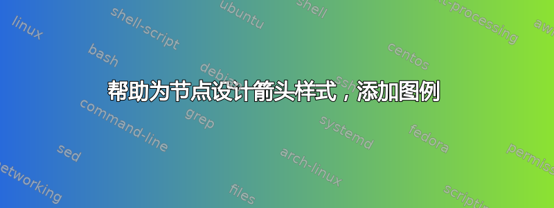
我已经使用了非常基础的知识来tikz制作 LHS 上的图像(或顶部,取决于设备查看器),而我真正想要的是 RHS 上的图像(使用 mathematica 创建):


这是我使用的代码:
\documentclass{article}
\usepackage{tikz}
\usetikzlibrary{automata,arrows,calc,positioning}

\begin{document}

\begin{figure}%[H]
\centering
\begin{tikzpicture}[>=stealth', shorten >=1pt, auto,
node distance=2cm, scale=1,
transform shape, align=center,
state/.style={circle, draw, minimum size=2cm}],

\tikzset{arrowhead=2cm}

\node[state]  (GS) {Person};
\node[state,  right=of GS]  (G1) {work};
\node[state, above right=of GS] (G2) {family};
\node[state, above left=of GS] (G3) {friends};
\node[state, left=of GS] (G4) {partner \\wife};
\node[state, below left=of GS] (G5) {community};
\node[state, below right=of GS] (G6) {local \\agencies};

\path[->] (GS) edge node {} (G1)
          (GS) edge node {} (G2)
          (GS) edge node {} (G3)
          (GS) edge node {} (G4)
          (GS) edge node {} (G5)
          (GS) edge node {} (G6);

\end{tikzpicture}
\end{figure}
\end{document}
我曾尝试对箭头线进行图例和样式设置以获得所需效果,但未能成功。
答案1
首先请注意,您的代码给出了错误“I do not know the key '/tikz/arrowhead', to which you passed '2cm', and I am going to ignore it.没有这样的键来调整箭头提示的大小”,我认为这就是您想要做的(?)。
要实际修改提示大小,请加载arrows.meta库而不是旧的和已弃用的arrows库。arrows.meta定义一组新的提示,包括Stealth(注意大写 S),可以采用各种设置。例如,您可以使用
>={Stealth[width=7pt, length=8pt]}
以获得更大的提示。请注意,括号 ( {}) 是隐藏]解析器所必需的,否则该右括号将被视为\begin{tikzpicture}[...]
要制作虚线,使用dashed,例如绘制点划线
对于图例,画一条线,并在端点右侧添加一个节点,即类似于\draw (a,b) -- +(1.5,0) node[right] {foo};一些有用的坐标选择(a,b)。+之前的(1.5,0)表示它是一个相对坐标。 在下面的代码中,我将其相对于社区节点放置。
我还删除了每个的空节点edge,因为如果您不标记边,这些节点就不需要了。

\documentclass{article}
\usepackage{tikz}
\usetikzlibrary{
  automata,
  arrows.meta, % instead of the deprecated arrows
  calc,
  positioning
}

\begin{document}

\begin{figure}%[H]
\centering
\begin{tikzpicture}[
 >={Stealth[width=7pt, length=8pt]},
 shorten >=1pt, auto,
 node distance=2cm, scale=1,
 transform shape, align=center,
 state/.style={circle, draw, minimum size=2cm}
]

\node[state]  (GS) {Person};
\node[state,  right=of GS]  (G1) {work};
\node[state, above right=of GS] (G2) {family};
\node[state, above left=of GS] (G3) {friends};
\node[state, left=of GS] (G4) {partner \\wife};
\node[state, below left=of GS] (G5) {community};
\node[state, below right=of GS] (G6) {local \\agencies};

\path[->] (GS) edge (G1)
          (GS) edge[dashed] (G2)
          (GS) edge[dashed] (G3)
          (GS) edge[dashed] (G4)
          (GS) edge[dashed] (G5)
          (GS) edge[dashed] (G6);


\draw (G5.south west) ++(-1.5,-1.5) coordinate (tmp) -- +(1.5,0) node[right] {Relationship};
\draw [dashed] (tmp)  ++(0,-0.5) -- +(1.5,0) node[right] {Relationship needed};
\end{tikzpicture}
\end{figure}
\end{document}
答案2
\documentclass{article}
\usepackage{tikz}
\usetikzlibrary{automata,arrows,calc,positioning,arrows.meta}

\begin{document}

\begin{figure}%[H]
\centering
\begin{tikzpicture}[>=stealth', shorten >=1pt, auto,
node distance=2cm, scale=1,
transform shape, align=center,
state/.style={circle, draw, minimum size=2cm}],

\node[state]  (GS) {Person};
\node[state,  right=of GS]  (G1) {work};
\node[state, above right=of GS] (G2) {family};
\node[state, above left=of GS] (G3) {friends};
\node[state, left=of GS] (G4) {partner \\wife};
\node[state, below left=of GS] (G5) {community};
\node[state, below right=of GS] (G6) {local \\agencies};

\path[-{Stealth[length=5mm]},dashed] (GS) edge node {} (G1)
          (GS) edge node {} (G2)
          (GS) edge node {} (G3)
          (GS) edge node {} (G4)
          (GS) edge node {} (G5);

\path[-{Stealth[length=5mm]},solid] (GS) edge node {} (G6);
\draw ([yshift=-2cm] current bounding box.south west) -- ++(2cm,0) node[xshift=1.2cm]{Relationship};
\draw[dashed] ([yshift=-1cm] current bounding box.south west) -- ++(2cm,0) node[xshift=1.8cm]{Relationship needed};
\end{tikzpicture}
\end{figure}
\end{document}

有了新的约束。我从来都不是“定位”的忠实粉丝
\documentclass{article}
\usepackage{tikz}
\usetikzlibrary{automata,arrows,arrows.meta}

\begin{document}

\begin{figure}%[H]
\centering
\begin{tikzpicture}[>=stealth', shorten >=1pt, auto,  align=center,
state/.style={circle, draw, minimum size=2cm}],

\node[state]  (GS) {Person};
\node[state] at  (canvas polar cs:angle=90,radius=4cm) (G1) {work};
\node[state] at  (canvas polar cs:angle=18,radius=4cm) (G2) {family};
\node[state] at  (canvas polar cs:angle=162,radius=4cm) (G3) {friends};
\node[state] at  (canvas polar cs:angle=234,radius=4cm) (G5) {community};
\node[state] at  (canvas polar cs:angle=-54,radius=4cm) (G6) {local \\agencies};

\path[-{Stealth[length=5mm]},dashed] (GS) edge node {} (G1)
          (GS) edge node {} (G2)
          (GS) edge node {} (G3)
          (GS) edge node {} (G5);

\path[-{Stealth[length=5mm]},solid] (GS) edge node {} (G6);
\draw ([yshift=-2cm] current bounding box.south west) -- ++(2cm,0) node[right]{Relationship};
\draw[dashed] ([yshift=-1cm] current bounding box.south west) -- ++(2cm,0) node[right]{Relationship needed};
\end{tikzpicture}
\end{figure}
\end{document}

答案3
五个卫星节点,使用极坐标:
\documentclass{article}
\usepackage{tikz}
\usetikzlibrary{arrows.meta}

\begin{document}
    \begin{figure}[ht]
    \centering
\begin{tikzpicture}[
         C/.style = {circle, draw, semithick,
                     text width=4em, align=center,
                     inner sep=2pt, outer sep=2pt},
every edge/.style = {draw, -{Stealth[angle=60:5pt 6]}, semithick} % <---
                    ]
\node[C] (GS) {Person};
\foreach \i [count=\j] in {work, family, friends, partner wife, local agencies}
{
    \node[C] (s\j) at (\j*360/5:33mm) {\i};    % five satellite nodes
}
\path   (GS) edge[dashed] (s1)
             edge[dashed] (s2)
             edge[dashed] (s3)
             edge[dashed] (s4)
             edge         (s5);
% legend
\draw           (GS) ++ (-4,-4.0) -- ++ (1,0) node[right] {Relationship};
\draw[dashed]   (GS) ++ (-4,-4.5) -- ++ (1,0) node[right] {Relationship needed};
\end{tikzpicture}
    \end{figure}
\end{document}
您可以在 Ti 中找到有关箭头样式的更多信息钾Z & PGFF 手册 3.1.9a 版,第 16.5 章参考:箭尖,第 211 页。使用的箭头样式在第 212 页和 215 页(针对直刺)中描述。

附录 在某些情况下,当你想将图像旋转某个角度时,只需将此角度添加到锚点的计算中。例如:
\node[C] (s\j) at (<angle offset> +\j*360/5:33mm) {\i};
当您希望节点以 90 度“工作”时,情况如下:
\node[C] (s\j) at (90-360/5+\j*360/5:33mm) {\i}; % five satellite nodes with angle offset (90-360/5) =18 degree
在上面的 MWE 中考虑到这一点,它将产生以下图像:
