

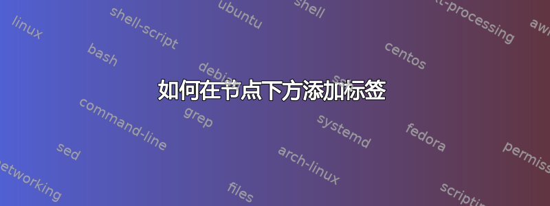
下图是通过手动定位注释制作的:

我希望让代码更容易适应。例如,通过添加更多带注释的节点使其更容易扩展。
如果可以自动计算注释的定位以提供类似的对齐,那将会有所帮助。
也许还有更多可以构建的内容以方便阅读/修改。
\documentclass{standalone}
\usepackage{tikz}
\usetikzlibrary{arrows}
\usetikzlibrary{positioning}
\begin{document}
    \begin{tikzpicture}[]
        \draw[->] (0,0) node[left,font=\Large] (X) {A} -- (2,0) node[right,font=\Large] (Y) {Y};
        \node[below left=0.2 and -0.3,font=\tiny] (X_text) at (0, 0) {Asperine};
        \node[below right=0.2 and -0.15,font=\tiny] (Y_text) at (2, 0) {Stroke};
     \end{tikzpicture}
\end{document}
答案1
node您可以在命令中包含s 和labels来在一行中完成此操作\draw:

\draw[->](0,0)node[left, label={[label distance=-1mm]below:{\tiny Asperine}}]{\Large A}
    --(2,0)node[right, label={[label distance=-1mm]below:{\tiny Stroke}}]{\Large Y};
请参阅章节17.10 标签和 Pin 选项在 PGF/TikZ Manual 手册中。
但是使用 定义样式会更有效(特别是如果您计划在文档中的几个不同位置使用它)tikzset。这样,您可以在一个位置进行更改,它将更改文档中的所有位置。
\documentclass{article}

\usepackage{tikz}
\tikzset{mynode/.style={font=\Large, label={[label distance=-1mm]below:{\tiny #1}}}}

\begin{document}

\begin{tikzpicture}
\draw[->](0,0)node[left, mynode=Asperine]{A}--(2,0)node[right, mynode=Stroke]{Y};
\end{tikzpicture}

\end{document}
或者,如果您想将节点(而不是箭头末端)放置在特定位置,您可以使用以下命令:

\documentclass{article}

\usepackage{tikz}
\tikzset{
    mynode/.style={font=\Large, label={[label distance=-1mm]below:{\tiny #1}}}
}

\begin{document}

\begin{tikzpicture}
\node[mynode=Asperine](A) at (0,0){A};
\node[mynode=Stroke](B) at (2,0){Y};
\draw[->](A)--(B);
\end{tikzpicture}

\end{document}
答案2
这是另一种使用多部分形状的节点的方法,请参阅tikz-manual 第 71.6 章中的“形状矩形分割”。如果您想定义更复杂的文本对象,这将很有用。
主要区别:
- 定义几个
rectangle splits,例如本例中的 3 - 定义自己的样式,如果有用的
node话nodepart
我画出了默认形状的轮廓,以便更好地看到这 3 个部分。我使用极坐标符号将连接器稍微“向上”移动。

\documentclass[10pt,border=3mm,tikz]{standalone}
\usetikzlibrary{arrows.meta}
\usetikzlibrary{shapes.multipart}

\begin{document}
 \begin{tikzpicture}[
    >={Stealth},    % providing some nicer arrow tips (make your choice)
    maj/.style={font={\Large},
                draw=teal!15,dashed,    % just to show the nodeparts shapes
                rectangle split,rectangle split parts=3},% <<< important
    anno/.style={font={\tiny}},
    cmnt/.style={font={\tiny\itshape},blue},
 ]
    % ~~~ nodes ~~~~~~~
    \node[maj] (A) at (0,0)
    {   A
        \nodepart[anno]{two} Asperine
        \nodepart[cmnt]{three} some comment
    };
    \node[maj] (Y) at (3,0)
    {   Y
        \nodepart[anno]{two} Stroke
        \nodepart[cmnt]{three} a different comment
        };

    % ~~~ connectors ~~~~~~
    \draw[->]               (A.25) -- (Y.160);
    \draw[->,orange,dotted] (A)    -- (Y);      % just for reference
 \end{tikzpicture}
\end{document}
答案3
这是其中一种方法。我建议不要一步做太多事情,因为很容易(甚至不能保证)迷失。基本思路:
- 单独行动
\node将s 与正文放在一起,例如下面给出的绝对值- 放置注释
\node- s,重复使用上述位置 - 通过您选择的线路连接
- 根据需要引入选项并将它们重构(移动)为样式,以便大量重复使用
- 做干净的代码工作一次又一次地获得回报
您的示例中存在一些主要错误:
- 如果你按照我的方法,左和右都是错误的,不需要
- 您希望
[anchor=north]注释节点位于south主节点的位置,以自动放置 - 对于更长的注释,您可能需要在 -style
align=center中引入anno并在节点中放入如下文本:{some\\longer\\text};
根据您预期的绘图或图表的复杂程度,您可能希望将maj和anno操作组合到一个\pic元素中(这里不做),您可以反复放置。您可能希望传递 2 个参数,即主参数和注释文本。
您可以使用上述方法重写代码。重写后的代码可能难以阅读,从而容易出现错误、故障等。不过,这只是个人喜好问题。

\documentclass[10pt,border=3mm,tikz]{standalone}
    %\usetikzlibrary{arrows}
    %\usetikzlibrary{positioning}
\usetikzlibrary{arrows.meta}

\begin{document}
 \begin{tikzpicture}[
    >={Stealth},    % providing some nicer arrow tips (make your choice)
    anno/.style={anchor=north,font={\tiny}},
    maj/.style={font={\Large}},
 ]
    % ~~~ nodes ~~~~~~~
    \node[maj] (A) at (0,0) {A};
    \node[maj] (Y) at (3,0) {Y};

    % ~~~ annotations ~~~
    \node[anno] at (A.south) {Asperine};
    \node[anno] at (Y.south) {Stroke};

    % ~~~ connectors ~~~~~~
    \draw[->] (A) -- (Y);
 \end{tikzpicture}
\end{document}