

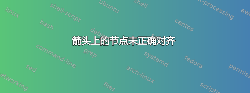
我为自动机编写了 LaTeX,如下所示:

如您所见,从 q1 到 q3 的箭头上的“b”位置低于从 q3 到 q2 的箭头上的“a、b、c”。
而且,从 q2 到 q3 的边缘上的“b”的位置低于从 q3 到 q1 的箭头上的“a, c”。
我希望两个节点组合能够很好地对齐,即在同一基线上。但是,这四个节点不必都在同一条线上。
我觉得我的代码应该可以自行完成这个任务,但是不知为何却不起作用。为什么?
这是我的代码。我用注释标记了两个节点组合:
\documentclass[border=5mm]{standalone}

\usepackage{tikz}
\usetikzlibrary{automata,arrows,calc,positioning}

\begin{document}
\begin{tikzpicture}[->,node distance=25mm]
\node[state,initial,accepting] (q0) {$q_0$};
\node[state,right=of q0] (q1) {$q_1$};
\node[state,right=of q1] (q2) {$q_2$};
\node[state,below=of $(q1)!0.5!(q2)$] (q3) {$q_3$};
\node[state,accepting,right=of q2] (q4) {$q_4$};

\draw (q0) edge[loop above] node[above] {a, b} (q0);
\draw (q0) -- node[above] {b, c} ++ (q1);
\draw (q1) edge[loop above] node[above] {a, c} (q1);
\draw (q1) edge[bend left] node[above] {a, b, c} (q2);
\draw (q2) -- node[below] {a, c} ++ (q1);
\draw (q2) edge[bend left] node[right] {b} (q3);             % ! duo B
\draw (q3) -- node[above left] {a, b, c} ++ (q2);            % ! duo A
\draw (q3) edge[bend left] node[left] {a, c} (q1);           % ! duo B
\draw (q1) -- node[above right] {b} ++ (q3);                 % ! duo A
\draw (q2) edge[loop above] node[above] {a, b, c} (q2);
\draw (q2) -- node[above] {c} ++ (q4);
\draw (q1) edge[out=60,in=120] node[above] {c} (q4);
\end{tikzpicture}
\end{document}
答案1
为这些节点添加\strut或定义text depth。我还适当地将above left改为left和above right改为right。
\documentclass[border=5mm]{standalone}

\usepackage{tikz}
\usetikzlibrary{automata,arrows,calc,positioning}

\begin{document}
\begin{tikzpicture}[->,node distance=25mm]
\node[state,initial,accepting] (q0) {$q_0$};
\node[state,right=of q0] (q1) {$q_1$};
\node[state,right=of q1] (q2) {$q_2$};
\node[state,below=of $(q1)!0.5!(q2)$] (q3) {$q_3$};
\node[state,accepting,right=of q2] (q4) {$q_4$};

\draw (q0) edge[loop above] node[above] {a, b} (q0);
\draw (q0) -- node[above] {b, c} ++ (q1);
\draw (q1) edge[loop above] node[above] {a, c} (q1);
\draw (q1) edge[bend left] node[above] {a, b, c} (q2);
\draw (q2) -- node[below] {a, c} ++ (q1);
\draw (q2) edge[bend left] node[right] {\strut b} (q3);             % ! duo B
\draw (q3) -- node[left] {\strut a, b, c} ++ (q2);            % ! duo A
\draw (q3) edge[bend left] node[left] {\strut a, c} (q1);           % ! duo B
\draw (q1) -- node[right] {\strut b} ++ (q3);                 % ! duo A
\draw (q2) edge[loop above] node[above] {a, b, c} (q2);
\draw (q2) -- node[above] {c} ++ (q4);
\draw (q1) edge[out=60,in=120] node[above] {c} (q4);
\end{tikzpicture}
\end{document}

答案2
首先,我要text height=1ex, text depth=0pt在tikzpictures 选项中添加选项,以强制所有标签具有相同的(垂直)尺寸。
这样做之后,问题
如您所见,从 q1 到 q3 的箭头上的“b”位置低于从 q3 到 q2 的箭头上的“a、b、c”。
而且,从 q2 到 q3 的边缘上的“b”的位置低于从 q3 到 q1 的箭头上的“a, c”。
被神奇地修复了。
另一种奇特的解决方案是命名重要节点,比如带有 的节点,a,b,c并b根据重要节点的位置定义 的位置。即:
\draw (q1) -- node[shift={(label-abc.west)}, xshift=-3.5mm] {b} ++ (q3);
完整代码:
\documentclass[border=5mm]{standalone}

\usepackage{tikz}
\usetikzlibrary{automata,arrows,calc,positioning}

\begin{document}
\begin{tikzpicture}[->,node distance=25mm, text height=1ex, text depth=0pt]
\node[state,initial,accepting] (q0) {$q_0$};
\node[state,right=of q0] (q1) {$q_1$};
\node[state,right=of q1] (q2) {$q_2$};
\node[state,below=of $(q1)!0.5!(q2)$] (q3) {$q_3$};
\node[state,accepting,right=of q2] (q4) {$q_4$};

\draw (q0) edge[loop above] node[above] {a, b} (q0);
\draw (q0) -- node[above] {b, c} ++ (q1);
\draw (q1) edge[loop above] node[above] {a, c} (q1);
\draw (q1) edge[bend left] node[above] {a, b, c} (q2);
\draw (q2) -- node[below] {a, c} ++ (q1);
\draw (q2) edge[bend left] node[right] {b} (q3);             % ! duo B
\draw (q3) -- node[above left](label-abc) {a, b, c} ++ (q2); % ! duo A
\draw (q3) edge[bend left] node[left] {a, c} (q1);           % ! duo B
\draw (q1) -- node[shift={(label-abc.west)}, xshift=-3.5mm] {b} ++ (q3); % ! duo A
\draw (q2) edge[loop above] node[above] {a, b, c} (q2);
\draw (q2) -- node[above] {c} ++ (q4);
\draw (q1) edge[out=60,in=120] node[above] {c} (q4);
\end{tikzpicture}
\end{document}

注意:同时设置text height和text depth确实有助于解决以下情况页,问,G等等。
例如:
\documentclass[border=5mm]{standalone}

\usepackage{tikz}
\usetikzlibrary{automata,arrows,calc,positioning,fit}

\begin{document}
\begin{tikzpicture}[->,node distance=25mm, text height=1ex, text depth=0pt]
\node[state,initial,accepting] (q0) {$q_0$};
\node[state,right=of q0] (q1) {$q_1$};
\node[state,right=of q1] (q2) {$q_2$};
\node[state,below=of $(q1)!0.5!(q2)$] (q3) {$q_3$};
\node[state,accepting,right=of q2] (q4) {$q_4$};

\draw (q0) edge[loop above] node[above] {a, b} (q0);
\draw (q0) -- node[above] {b, c} ++ (q1);
\draw (q1) edge[loop above] node[above] {a, c} (q1);
\draw (q1) edge[bend left] node[above] {a, b, c} (q2);
\draw (q2) -- node[below] {a, c} ++ (q1);
\draw (q2) edge[bend left] node[right] (label-g) {g} (q3);             % ! duo B
\draw (q3) -- node[draw,above left](label-abc) {a, b, c} ++ (q2); % ! duo A
\draw (q3) edge[bend left] node[left] (label-ac) {a, c} (q1);           % ! duo B
\draw (q1) -- node[draw,above right] {q} ++ (q3);                 % ! duo A
\draw (q2) edge[loop above] node[above] {a, b, c} (q2);
\draw (q2) -- node[above] {c} ++ (q4);
\draw (q1) edge[out=60,in=120] node[above] {c} (q4);

\node[draw,fit=(label-g)(label-ac)]{};
\draw (label-ac.base)--(label-g.base);
\end{tikzpicture}
\end{document}
结果:

答案3
大部分都是题外话,用于练习如何使图表代码更短 :-)。还给出了一些额外的解释,并建议使用tikz库“quotes”。
正如其他答案所述,您需要在边缘标签中定义逗号的空格。这可以通过两种方式完成:
- 按提议克劳迪奥·菲安德里诺:确定
text height=1ex并设置text depth=0pt。这是因为字母b和逗号分别接触节点的顶部和底部边框 - 根据@user11232的建议:在每个倾斜边缘标签的节点内容上使用支柱,使这些节点的高度和深度相等
在下面的 mwe 中我遵循克劳迪奥·菲安德里诺方法,但是节点大小的定义不同,而且在我看来更正确。对于边标签使用edge quotes:
\documentclass[tikz, border=3mm]{standalone}
\usetikzlibrary{arrows.meta, automata,
                calc,
                positioning,
                quotes}

\begin{document}
    \begin{tikzpicture}[-Straight Barb,
node distance = 25mm,
         auto = left,
every edge quotes/.style = {inner sep=1pt,     % that labels are closer to edges
                            text height=1.5ex, % equal height,
                            text depth=2pt,    % space for commas
                                               % however this depth is not sufficient for letters as p,q, ...
                                               % for them is better 0.25ex or slightly more
                            font=\small}       % smaller letters, gives a nicer result
                        ]
\node (q0)  [state,initial,accepting]         {$q_0$};
\node (q1)  [state,right=of q0]               {$q_1$};
\node (q2)  [state,right=of q1]               {$q_2$};
\node (q3)  [state,below=of $(q1)!0.5!(q2)$]  {$q_3$};
\node (q4)  [state,accepting,right=of q2]     {$q_4$};
%
\draw   (q0) edge[loop above, "{a, b}"]     ()
        (q0) edge["{b, c}"]                 (q1)
        (q1) edge[loop above, "{a, c}"]     ()
        (q1) edge[bend left, "{a, b, c}"]   (q2)
        (q2) edge["{a, c}"]                 (q1)
        (q2) edge[loop above, "{a, b, c}"]  ()
        (q2) edge[bend left, "b"]           (q3)    % ! duo B
        (q2) edge["c"]                      (q4)
        (q3) edge["{a, b, c}"]              (q2)    % ! duo A
        (q3) edge[bend left, "{a, c}"]      (q1)    % ! duo B
        (q1) edge["b"]                      (q3)    % ! duo A
        (q1) edge[out=60,in=120, "c"]       (q4);
\end{tikzpicture}
\end{document}
