

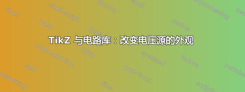
我怎样才能改变 TikZ 中的外观voltage source。
图片显示了实际结果和期望结果(手动伪造)
代码
\documentclass{minimal}

\usepackage{tikz}
\usetikzlibrary{circuits.ee.IEC}

\begin{document}
\begin{tikzpicture}[circuit ee IEC]
  \node at (0,0) [anchor=south west] {desired};
  \node at (0,2) [anchor=south west] {actual};
% actual:
  \draw (0,2) to[voltage source={info={$U_\sim$}}] ++(5,0);
% desired (faked):
  \draw [radius=1pt,fill=white] (0,0) -- ++(2.25,0) circle ++(0.5,0) circle --++(2.25,0);
  \fill [radius=0.8pt,fill=white] (0,0) -- ++(2.25,0) circle ++(0.5,0) circle --++(2.25,0);
  \path (0,0) -- (5,0) node [midway,above] {$U_\sim$};
\end{tikzpicture}
\end{document}
答案1
这是在电路中使用该形状的新形状和随附样式。定义新的电路符号一开始可能会有点令人困惑:要定义一个全新的符号(不基于圆形或二极管的符号),首先需要定义一个 PGF 形状,然后在 TikZ 中声明一个新的电路符号,然后将此符号的图形设置为使用新定义的形状。

\documentclass{standalone}
\usepackage{tikz}
\usetikzlibrary{circuits.ee.IEC}

\begin{document}

\makeatletter
\pgfdeclareshape{alt voltage source}    % Declare the PGF shape for the voltage source
{
  \inheritsavedanchors[from=rectangle ee]   % Start with the anchors of a rectangle
  \inheritanchor[from=rectangle ee]{center}
  \inheritanchor[from=rectangle ee]{north}
  \inheritanchor[from=rectangle ee]{south}
  \inheritanchor[from=rectangle ee]{east}
  \inheritanchor[from=rectangle ee]{west}
  \inheritanchor[from=rectangle ee]{north east}
  \inheritanchor[from=rectangle ee]{north west}
  \inheritanchor[from=rectangle ee]{south east}
  \inheritanchor[from=rectangle ee]{south west}
  \inheritanchor[from=rectangle ee]{input}
  \inheritanchor[from=rectangle ee]{output}
  \inheritanchorborder[from=rectangle ee]

  \backgroundpath{  % Draw the actual bits
    \pgf@process{\pgfpointadd{\southwest}{\pgfpoint{\pgfkeysvalueof{/pgf/outer xsep}}{\pgfkeysvalueof{/pgf/outer ysep}}}} % Get lower left corner
    \pgf@xa=\pgf@x % Store left x-coordinate in macro
    \pgf@process{\pgfpointadd{\northeast}{\pgfpoint{-\pgfkeysvalueof{/pgf/outer xsep}}{\pgfkeysvalueof{/pgf/outer ysep}}}} % Get upper right corner
    \pgf@xb=\pgf@x % Store right x-coordinate in macro
    \pgfmathsetlength\pgfutil@tempdima{(\pgf@xb-\pgf@xa)/12} % calculate radius of point: 1/12th of width (this is what 'var make contact IEC' uses)
    {\pgfpathcircle{\pgfpoint{\pgf@xa+\pgfutil@tempdima}{0pt}}{\pgfutil@tempdima}} % Draw circles in own groups, to protect the macros
    {\pgfpathcircle{\pgfpoint{\pgf@xb-\pgfutil@tempdima}{0pt}}{\pgfutil@tempdima}}
  }
}
\makeatother

\tikzset{
    circuit declare symbol=alt voltage source, % Declare the circuit symbol
    set alt voltage source graphic={ % Define how to display the circuit symbol
        circuit symbol lines, % Draw with the `lines` style, not the `wires` style
        circuit symbol size=width 2 height 0.15, % The size of the bounding box
        transform shape, % The symbol rotates and scales
        shape=alt voltage source % Use the shape we defined earlier
    }
}
\begin{tikzpicture}[
    circuit ee IEC,
    set voltage source graphic=alt voltage source % redefine the normal voltage source
]
  \draw (0,0) to [alt voltage source={info={$U_\sim$}}] ++(2,0);
\end{tikzpicture}
\end{document}