


答案1
评论
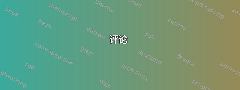
我用过 Ti钾Z 代表此解决方案。我为顶点创建了一个样式,以避免重新输入。图形在 x 方向上移动,而不是指定移动的坐标。边界框需要手动调整,因为贝塞尔曲线的控制点超出了可见绘图的限制。
执行
\documentclass[tikz]{standalone}
\usetikzlibrary{calc}
\tikzset{
    vertex/.style = {
        circle,
        fill=black,
        outer sep=2pt,
        inner sep=1pt
    }
}
\begin{document}
\begin{tikzpicture}[>=stealth]
    % We need to adjust the bounding box manually
    % as the control points enlarge it.
    \path[use as bounding box] (-1.5,-0.5) rectangle (10.5,5);

    \begin{scope}[xshift=0cm]
        \coordinate (o) at (0,0);
        \node[below] at (o) {root};
        \draw node[vertex] (a) at (0,3) {};
        \draw node[vertex] (b) at (0,4) {};
        \node[above] at (b) {$v$};

        \draw[->] (0,0) -- (a) (a) -- (b);
        \draw[blue,->] (b) .. controls (-1,4.5) .. node[below right] {$e_1$} (0,2);
        \draw[blue,->] (b) .. controls (1,4.5) and (-3,7) .. node[below right] {$e_2$} (0,1);
    \end{scope}

    \begin{scope}[xshift=3cm]
        \coordinate (o) at (0,0);
        \node[below] at (o) {root};
        \draw node[vertex] (a) at (0,3) {};
        \draw node[vertex] (b) at (0,4) {};
        \node[above] at (b) {$v$};

        \draw[->] (0,0) -- (a) (a) -- (b);
        \draw[blue,->] (b) .. controls (-1,4.5) .. node[below right] {$e_1$} (0,1);
        \draw[red,->] (b) .. controls (1,4.5) .. node[below left] {$e_2$} (0,2);
    \end{scope}

    \begin{scope}[xshift=6cm]
        \coordinate (o) at (0,0);
        \node[below] at (o) {root};
        \draw node[vertex] (a) at (0,3) {};
        \draw node[vertex] (b) at (0,4) {};
        \node[above] at (b) {$v$};

        \draw[->] (0,0) -- (a) (a) -- (b);
        \draw[blue,->] (b) .. controls (-1,4.5) .. node[below right] {$e_1$} (0,2);
        \draw[red,->] (b) .. controls (1,4.5) .. node[below left] {$e_2$} (0,1);
    \end{scope}

    \begin{scope}[xshift=9cm]
        \coordinate (o) at (0,0);
        \node[below] at (o) {root};
        \draw node[vertex] (a) at (0,3) {};
        \draw node[vertex] (b) at (0,4) {};
        \node[above] at (b) {$v$};

        \draw[->] (0,0) -- (a) (a) -- (b);
        \draw[red,->] (b) .. controls (1,4.5) .. node[below left] {$e_1$} (0,2);
        \draw[red,->] (b) .. controls (-1,4.5) and (3,7) .. node[below left] {$e_2$} (0,1);
    \end{scope}
\end{tikzpicture}

\begin{tikzpicture}[>=stealth]
    % We need to adjust the bounding box manually
    % as the control points enlarge it.
    \path[use as bounding box] (-1,-0.5) rectangle (1.5,5.5);

    \coordinate (o) at (0,0);
    \node[below] at (o) {root};
    \draw node[vertex] (a) at (0,1) {};
    \draw node[vertex] (b) at (0,2) {};
    \draw node[vertex] (c) at (0,3) {};
    \draw node[vertex] (d) at (0,4) {};
    \node[above] at (d) {$v$};

    \draw (d) node[left] {$e_1$} -- (-0.5,4.5);
    \filldraw[draw=blue,fill=blue!50]
        (-0.5,4.5) .. controls (-1,5) and (-0.75,4.5) .. ($(c)+(180:4pt)$)
        arc[start angle=180, end angle=270, radius=4pt]
        -- ($(b)+(90:4pt)$) .. controls (-1,5) .. (-0.5,4.5);
    \draw (d) node[right] {$e_2$} -- (0.5,4.5);
    \filldraw[draw=red,fill=red!50]
        (0.5,4.5) .. controls (1,5) and (0.75,4.5) .. ($(c)+(0:4pt)$)
        arc[start angle=0, end angle=-90, radius=4pt]
        -- ($(b)+(90:4pt)$) arc[start angle=90, end angle=0, radius=4pt]
        ($(b)+(0:4pt)$) .. controls (1,5) .. (0.5,4.5);
    \draw[red,thick,->] (0.5,4.5) .. controls (1,5) .. ($(b)+(0:4pt)$);
    \draw[->] (-0.5,4.5) .. controls (-1,5) and (3,7) .. (a);

    \draw[->] (o) -- (a) (a) -- (b) (b) -- (c) (c) -- node[left] {$e$} (d);
\end{tikzpicture}
\end{document}

