

在我的以下代码中:
- 如何为 DCE 角创建漂亮的标记角度?
- 我怎样才能改变空间中 BAC 角前方的 ALPHA 位置?
\documentclass{article}
\usepackage{tikz,tikz-3dplot}
\usepackage{tkz-euclide}
\usetkzobj{all}

\begin{document}
  \tdplotsetmaincoords{60}{120}

  \begin{tikzpicture}[
    scale=3,
    tdplot_main_coords,
    axis/.style={->,blue,thick},
    vector/.style={-stealth,red,very thick},
    vector guide/.style={dashed,red,thick}
  ]

    % standard tikz coordinate definition using x, y, z coords
    \coordinate (O) at (0,0,0);
    \coordinate (A) at (1,0,2);
    \coordinate (B) at (.5,.86603,3);
    \coordinate (C) at (0,0,1);
    \coordinate (D) at (.5,.86603,0);
    \coordinate (E) at (1,0,3);
    \coordinate (F) at (0,0,3);
    \coordinate (H) at (1,0,0);

    % tikz-3dplot coordinate definition using r, theta, phi coords
    \tdplotsetcoord{P}{.8}{55}{60}

    % draw axes
    \draw[axis] (0,0,0) -- (2,0,0) node[anchor=north east]{$x$};
    \draw[axis] (0,0,0) -- (0,2,0) node[anchor=north west]{$y$};
    \draw[axis] (0,0,0) -- (0,0,4) node[anchor=south]{$z$};

    \fill[gray!20] (O) -- (H) -- (E) -- (F) -- cycle;
    % \fill[green!50] (O) -- (D) -- (B) -- (F) -- cycle;
    \fill[blue!20] (B) -- (E) -- (F) -- cycle;
    \fill[blue!20] (O) -- (D) -- (H) -- cycle;

    \fill[black] (O) circle (1pt) node[right] {$O$};
    \fill[black] (A) circle (1pt) node[left] {$A$};
    \fill[black] (B) circle (1pt) node[right] {$B$};
    \fill[black] (C) circle (1pt) node[right] {$C$};
    \fill[black] (D) circle (1pt) node[right] {$D$};
    \fill[black] (E) circle (1pt) node[left] {$E$};
    \fill[black] (F) circle (1pt) node[right] {$F$};
    \fill[black] (H) circle (1pt) node[below] {$H$};

    \draw[ultra thick] (O) -- (F);
    \draw[thick] (O) -- (H);
    \draw[thick] (O) -- (D);
    \draw[thick] (D) -- (H);
    \draw[thick] (H) -- (A);
    \draw[thick] (A) -- (E);
    \draw[thick] (F) -- (B);
    \draw[thick] (B) -- (E);
    \draw[thick] (E) -- (F);
    \draw[thick,red] (B) -- (A);
    \draw[thick,red] (A) -- (C);
    \draw[thick,red] (C) -- (D);
    \draw[thick] (B) -- (D);

    \tkzMarkAngle[fill=orange,size=0.2cm,opacity=.4](C,A,B)
    \tkzLabelAngle[above left,pos=0.3](C,A,B){$\alpha$}
    \tkzMarkAngle[fill=orange,size=0.15cm,opacity=.4](A,C,D)
    \tkzLabelAngle[above left,pos=0.3,font=\small](A,C,D){$\alpha$}
  \end{tikzpicture}
\end{document}
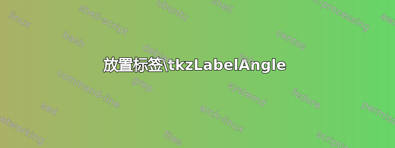
我的代码的结果。

答案1
让我按相反的顺序来回答这两个子问题。
放置标签\tkzLabelAngle
\tkzLabelAngle将标签放置在角的平分线上。参数pos给出标签在该线上的位置,作为标准长度的比例。其他参数例如above相对于参数指定的点pos。要将标签进一步向方向移动,above您可以编写类似 的内容above=5pt。以下是标有不同值的直角pos:

\documentclass{article}
\usepackage{tikz}
\usepackage{tkz-euclide}
\usetkzobj{all}

\begin{document}

\begin{tikzpicture}[scale=5]
  \coordinate (A) at (1,0);
  \coordinate (B) at (0,0);
  \coordinate (C) at (0,1);
  \draw (A) -- (B) -- (C);
  \tkzMarkAngle[fill=orange,size=0.3,opacity=0.4](A,B,C);
  \tkzLabelAngle[pos=0.1](A,B,C){$0.1$}
  \tkzLabelAngle[pos=0.3](A,B,C){$0.3$}
  \tkzLabelAngle[pos=0.5](A,B,C){$0.5$}
  \tkzLabelAngle[pos=0.5,above](A,B,C){$0.5$ above}
  \tkzLabelAngle[pos=0.5,above=20pt](A,B,C){$0.5$ above}
  \tkzLabelAngle(A,B,C){$1$}
\end{tikzpicture}

\end{document}
不幸的是,tkz-euclide有时会得到错误的角平分线方向:

\documentclass{article}
\usepackage{tikz}
\usepackage{tkz-euclide}
\usetkzobj{all}

\begin{document}

\begin{tikzpicture}[scale=5]
  \coordinate (A) at (1,1);
  \coordinate (B) at (0,0);
  \coordinate (C) at (1,-1);
  \draw (A) -- (B) -- (C);
  \tkzMarkAngle[fill=orange,size=0.3,opacity=0.4](A,B,C);
  \tkzLabelAngle[pos=0.1](A,B,C){$0.1$}
  \tkzLabelAngle[pos=0.3](A,B,C){$0.3$}
  \tkzLabelAngle[pos=0.5](A,B,C){$0.5$}
  \tkzLabelAngle[pos=0.5,above](A,B,C){$0.5$ above}
  \tkzLabelAngle[pos=0.5,above=20pt](A,B,C){$0.5$ above}
  \tkzLabelAngle(A,B,C){$1$}
\end{tikzpicture}

\end{document}
这就是在 处的角度发生的情况A。您可以通过指定负参数来弥补这一点pos。我可能会使用普通的tikz节点放置来实现这一点,如下面给出的代码所示。
角度 DCE 的标记
您可以使用与其他角度相同的方法。但是,节点处有很多东西C,因此需要调整定位。我还建议为角度添加引导边缘(虚线)并稍微旋转视图以提供帮助。将它们放在一起可得到:

\documentclass{article}
\usepackage{tikz,tikz-3dplot}
\usepackage{tkz-euclide}
\usetkzobj{all}

\begin{document}
  \tdplotsetmaincoords{60}{125}

  \begin{tikzpicture}[
    scale=3,
    tdplot_main_coords,
    axis/.style={->,blue,thick},
    vector/.style={-stealth,red,very thick},
    vector guide/.style={dashed,red,thick}
  ]

    % standard tikz coordinate definition using x, y, z coords
    \coordinate (O) at (0,0,0);
    \coordinate (A) at (1,0,2);
    \coordinate (B) at (.5,.86603,3);
    \coordinate (C) at (0,0,1);
    \coordinate (D) at (.5,.86603,0);
    \coordinate (E) at (1,0,3);
    \coordinate (F) at (0,0,3);
    \coordinate (H) at (1,0,0);

    % tikz-3dplot coordinate definition using r, theta, phi coords
    \tdplotsetcoord{P}{.8}{55}{60}

    % draw axes
    \draw[axis] (0,0,0) -- (2,0,0) node[anchor=north east]{$x$};
    \draw[axis] (0,0,0) -- (0,2,0) node[anchor=north west]{$y$};
    \draw[axis] (0,0,0) -- (0,0,4) node[anchor=south]{$z$};

    \fill[gray!20] (O) -- (H) -- (E) -- (F) -- cycle;
    \fill[blue!20] (B) -- (E) -- (F) -- cycle;
    \fill[blue!20] (O) -- (D) -- (H) -- cycle;

    \tkzMarkAngle[fill=orange,size=0.2cm,opacity=.4](C,A,B);
    \draw (A) node[right=2pt,font=\small] {$\alpha$};
    \tkzMarkAngle[fill=orange,size=0.15cm,opacity=.4](A,C,D);
    \draw (C) node[below left,font=\small] {$\gamma$};
    \tkzMarkAngle[fill=green,size=0.13cm,opacity=.6](D,C,E);
    \draw (C) node[right,font=\small] {$\beta$};

    \draw[ultra thick] (O) -- (F);
    \draw[thick] (O) -- (H);
    \draw[thick] (O) -- (D);
    \draw[thick] (D) -- (H);
    \draw[thick] (H) -- (A);
    \draw[thick] (A) -- (E);
    \draw[thick] (F) -- (B);
    \draw[thick] (B) -- (E);
    \draw[thick] (E) -- (F);
    \draw[thick,red] (B) -- (A);
    \draw[thick,red] (A) -- (C);
    \draw[thick,red] (C) -- (D);
    \draw[thick] (B) -- (D);
    \draw[thin,dashed] (D) -- (C) -- (E);

    \fill[black] (O) circle (1pt) node[above right] {$O$};
    \fill[black] (A) circle (1pt) node[left] {$A$};
    \fill[black] (B) circle (1pt) node[right] {$B$};
    \fill[black] (C) circle (1pt) node[above right=7pt] {$C$};
    \fill[black] (D) circle (1pt) node[right] {$D$};
    \fill[black] (E) circle (1pt) node[left] {$E$};
    \fill[black] (F) circle (1pt) node[above right] {$F$};
    \fill[black] (H) circle (1pt) node[below] {$H$};

  \end{tikzpicture}
\end{document}
您的图表中有两个“alpha”,因此我将其中一个重命名为“gamma”。我还更改了打印顺序,以便点标签位于图表的最上方。如上所述,我决定不使用\tkzLabelAngle普通的节点放置来标记角度。