

类似的问题是这里。如果我们给出顶点坐标和图的邻接矩阵的所有数据,如何使用 tikz、pstrick 或 tex 中的其他工具绘制它?
这是邻接矩阵和坐标的数据
Coordinates:{{0.809,0.588},{0.309,0.951},{-0.309,0.951},{-0.809,0.588},{-1.,0.},{-0.809,-0.588},{-0.309,-0.951},{0.309,-0.951},{0.809,-0.588},{1.,0.}}

Adjacency matrix: {{0,1,0,0,1,0,1,0,0,1},{1,0,1,0,0,1,0,1,0,0},{0,1,0,1,0,0,1,0,1,0},{0,0,1,0,1,0,0,1,0,1},{1,0,0,1,0,1,0,0,1,0},{0,1,0,0,1,0,1,0,0,1},{1,0,1,0,0,1,0,1,0,0},{0,1,0,1,0,0,1,0,1,0},{0,0,1,0,1,0,0,1,0,1},{1,0,0,1,0,1,0,0,1,0}}
有时数据量太大,无法将数据放入主 tex 文件中。最好从外部文件导入数据。这是一个大型数据文件。
答案1
一个简单的解决方案需要仅有的蒂克兹
\documentclass[tikz]{standalone}

\begin{document}
\begin{tikzpicture}[scale=2,vertex/.style={draw,circle}, arc/.style={draw,thick,->}]
    \foreach [count=\i] \coord in {(0.809,0.588),(0.309,0.951),(-0.309,0.951),(-0.809,0.588),(-1.,0.),(-0.809,-0.588),(-0.309,-0.951),(0.309,-0.951),(0.809,-0.588),(1.,0.)}{
        \node[vertex] (p\i) at \coord {\i};
    }

    \foreach [count=\r] \row in {{0,1,0,0,1,0,1,0,0,1},{1,0,1,0,0,1,0,1,0,0},{0,1,0,1,0,0,1,0,1,0},{0,0,1,0,1,0,0,1,0,1},{1,0,0,1,0,1,0,0,1,0},{0,1,0,0,1,0,1,0,0,1},{1,0,1,0,0,1,0,1,0,0},{0,1,0,1,0,0,1,0,1,0},{0,0,1,0,1,0,0,1,0,1},{1,0,0,1,0,1,0,0,1,0}}{
        \foreach [count=\c] \cell in \row{
            \ifnum\cell=1%
                \draw[arc] (p\r) edge (p\c);
            \fi
        }
    }
\end{tikzpicture}
\end{document}
这显然可以包装成接受邻接矩阵作为参数的宏。
相同的想法可用于生成 PGF3 图库(需要 LuaTeX)可解析的图形描述中的边。
这是一个“宏”版本,使用可定制的样式处理加权情况:
\documentclass[tikz]{standalone}

\newcommand{\graphfromadj}[3][arc/.try]{
    \foreach [count=\r] \row in {#3}{
        \foreach [count=\c] \cell in \row{
            \ifnum\cell=1%
                \draw[arc/.try=\cell, #1] (#2\r) edge (#2\c);
            \fi
        }
    }
}

\newcommand{\weigthgraphfromadj}[3][draw,->]{
    \foreach [count=\r] \row in {#3}{
        \foreach [count=\c] \cell in \row{
            \if0\cell%
            \else
                \draw[arc/.try=\cell, #1] (#2\r) edge node[arc label/.try=\cell]{\cell} (#2\c);
            \fi
        }
    }
}

\begin{document}
\begin{tikzpicture}[scale=5,
    vertex/.style={draw,circle},
    arc/.style={draw=blue!#10,thick,->},
    arc label/.style={fill=white, font=\tiny, inner sep=1pt}
    ]
    \foreach [count=\i] \coord in {(0.809,0.588),(0.309,0.951),(-0.309,0.951),(-0.809,0.588),(-1.,0.),(-0.809,-0.588),(-0.309,-0.951),(0.309,-0.951),(0.809,-0.588),(1.,0.)}{
        \node[vertex] (p\i) at \coord {\i};
    }

    \weigthgraphfromadj[bend left=10]{p}{{0,5,0,0,1,0,5,0,0,5},{2,0,1,0,0,5,0,2,0,0},{0,5,0,2,0,0,2,0,5,0},{0,0,7,0,5,0,0,2,0,5},{7,0,0,7,0,5,0,0,1,0},{0,5,0,0,2,0,5,0,0,1},{2,0,5,0,0,1,0,5,0,0},{0,7,0,5,0,0,2,0,1,0},{0,0,5,0,7,0,0,5,0,1},{5,0,0,5,0,1,0,0,1,0}}
\end{tikzpicture}
\end{document}

为了处理自循环,可以使用简单的 if,并且适当的样式可以调整设置(甚至每个节点):
\newcommand{\graphfromadj}[3][]{
    \foreach [count=\r] \row in {#3}{
        \foreach [count=\c] \cell in \row{
            \ifnum\cell>0%
                \ifnum\c=\r%
                    \draw[arc/.try=\cell] (#2\r) edge[loop arc/.try=\r] (#2\c);
                \else
                    \draw[arc/.try=\cell, #1] (#2\r) edge (#2\c);
                \fi
            \fi
        }
    }
}
使用这种方法检测双向边并以不同的方式绘制它们更加困难。
从外部文件导入
这是一种可能的方法,catchfile假设数据在文件中demo.dat
\documentclass[tikz]{standalone}
\usepackage{catchfile}

\newcommand{\graphfromadj}[3][]{
    \foreach [count=\r] \row in #3{
        \foreach [count=\c] \cell in \row{
            \ifnum\cell>0%
                \ifnum\c=\r%
                    \draw[arc/.try=\cell] (#2\r) edge[loop arc/.try=\r] (#2\c);
                \else
                    \draw[arc/.try=\cell, #1] (#2\r) edge (#2\c);
                \fi
            \fi
        }
    }
}

\CatchFileDef{\mymat}{demo.dat}{\endlinechar=-1 }

\begin{document}
\begin{tikzpicture}[
        scale=5,
        vertex/.style={draw,circle},
        arc/.style={draw=blue,thick,->},
        arc label/.style={fill=white, font=\tiny, inner sep=1pt},
        loop arc/.style={in=20,out=70,loop,min distance=.8mm}
    ]

    \foreach [count=\i] \coord in {(0.809,0.588),(0.309,0.951),(-0.309,0.951),(-0.809,0.588),(-1.,0.),(-0.809,-0.588),(-0.309,-0.951),(0.309,-0.951),(0.809,-0.588),(1.,0.)}{
        \node[vertex] (p\i) at \coord {\i};
    }

    \graphfromadj[bend left=10]{p}{\mymat}
\end{tikzpicture}
\end{document}
答案2

考虑使用Asymptote(TeXLive 发行版的一部分),它非常适合此类任务。下面是简要的MWE绘制方法
维基示例
在节点 5 中添加循环。此代码使用三个主要输入:邻接矩阵adj、坐标列表pair[] vcenter
和自循环方向列表(以度为单位)real[] SelfLoopDir。
// gmx.asy
//
settings.tex="pdflatex";
size(4cm);
import graph;
import fontsize;

defaultpen(fontsize(9pt));

texpreamble("\usepackage{lmodern}");

pair[] vcenter={
(120,130),
(60,250),
(100,380),
(230,360),
(200,220),
(340,430),
};

typedef int[][]Matrix;

Matrix adj={
{1, 1,  0,  0,  1,  0,},
{1, 0,  1,  0,  1,  0,},
{0, 1,  0,  1,  0,  0,},
{0, 0,  1,  0,  1,  1,},
{1, 1,  0,  1,  1,  0,},
{0, 0,  0,  1,  0,  0,},
};

real[] SelfLoopDir={-50,0,0,0,124,0};

int n=vcenter.length;

assert(n==adj.length && n==adj[0].length && n==SelfLoopDir.length,"Inconsistent input data. ");

real nodeR=40;
guide nodeShape=scale(nodeR)*unitcircle;

guide loop=(0,0){dir(-60)}..(nodeR*1.8,0)
           ..{dir(180+60)}cycle;

pen edgePen=orange+1bp;
pen nodeFgPen=deepblue+0.8bp;
pen nodeBgPen=lightgreen+0.8bp;

void drawNode(pair c){

  filldraw(shift(c.x,c.y)*nodeShape,nodeBgPen,nodeFgPen);
}

void drawEdge(int i, int j){
  pair p=vcenter[i], q=vcenter[j];
  if(i==j){
    draw(shift(p.x,p.y)*rotate(SelfLoopDir[i])*loop, edgePen);
  }else {
    draw(p--q, edgePen);
  }
}

void drawEdges(Matrix A){
  for(int i=0;i<n;++i){
    for(int j=0;j<=i;++j){
      if(A[i][j]>0){
        drawEdge(i,j);
      }
    }
  }
};

drawEdges(adj);

for(int i=0;i<vcenter.length;++i){
  drawNode(vcenter[i]);
}

for(int i=0;i<n;++i){
  label("$n_{"+string(i+1)+"}$",vcenter[i]);
}
用处理此代码asy gmx.asy,它将运行pdflatex以制作所有标签并将它们与图形一起组合成gmx.pdf。
我可以通过多种方式修改和增强代码,例如从文件读取数据或创建一个特殊的类来绘制事物。
答案3
这是一个鼠尾草方法,它使您可以访问计算机代数系统 Sage 和 Python 语言。有两种方法可以使用此软件包:在您的计算机上安装 Sage 并将其与 LaTeX 集成。在 Linux 中这不是一个问题,但在其他操作系统上可能会很麻烦。第二种方法是注册免费的SageMath 云帐户已为您设置好一切。您所要做的就是复制/粘贴下面的代码即可启动并运行。修改代码并不困难,但 Sage/graphs/LaTeX 有大量文档需要查阅,具体取决于您对输出的要求。我在下面放了一些关键链接。
您的评论(上文)表明您需要坐标以便“根据坐标绘制每个点,然后根据邻接矩阵链接它们”。使用 Sage,这些坐标不是必需的。图表格式部分为您提供了将图形导入 Sage 的 6 种方法。我将使用矩阵,对于第二张图,我将利用 Sage 丰富的图论知识来获取 Petersen 图。
\documentclass{article}
\usepackage{xcolor}
\usepackage{fullpage}% to get the URL in the margins
\usepackage{sagetex}
\usepackage{tikz}
\usepackage{tkz-graph,tkz-berge}
\usetikzlibrary{arrows,shapes}
\begin{document}
\begin{sagesilent}
M = Matrix([(-1,0,0,0,1,0,0,0,0,0,-1,0,0,0,0), \
(1,-1,0,0,0,0,0,0,0,0,0,-1,0,0,0),(0,1,-1,0,0,0,0,0,0,0,0,0,-1,0,0), \
(0,0,1,-1,0,0,0,0,0,0,0,0,0,-1,0),(0,0,0,1,-1,0,0,0,0,0,0,0,0,0,-1), \
(0,0,0,0,0,-1,0,0,0,1,1,0,0,0,0),(0,0,0,0,0,0,0,1,-1,0,0,1,0,0,0), \
(0,0,0,0,0,1,-1,0,0,0,0,0,1,0,0),(0,0,0,0,0,0,0,0,1,-1,0,0,0,1,0), \
(0,0,0,0,0,0,1,-1,0,0,0,0,0,0,1)])
g = Graph(M)
g.set_pos(g.layout_circular())
g.set_latex_options(graphic_size=(4,4), tkz_style = 'Custom',vertex_size = 0.2,    edge_thickness = 0.04, edge_color = 'black',vertex_labels=False)
\end{sagesilent}
The work done in \textbf{sagesilent} is invisible to us. When we're
ready to view the graph we can insert it as follows:\\
\begin{center}
\sage{g}
\end{center}
Of course, you can alter the size of the figure by adjusting the
numbers in \verb!graphic_size=(4,4)! to a different dimension.
Likewise, other parameters can be adjusted above. There is an
extensive list of plotting options. See the Sage URL:
\begin{verbatim}
http://www.sagemath.org/doc/reference/plotting/sage/graphs/graph_plot.html
\end{verbatim}
\begin{sagesilent}
from sage.graphs.graph_latex import check_tkz_graph
check_tkz_graph() # random - depends on TeX installation
h = graphs.PetersenGraph()
h.set_latex_options(graphic_size=(4.3,4.3), tkz_style = 'Art',vertex_size = 0.2, edge_thickness = 0.04,vertex_labels=False)
\end{sagesilent}
\begin{center}
\sage{h}
\end{center}
\end{document}
以下是 Sagemath Cloud 的输出:
注意几件事。首先,使用矩阵方法,图 g 是使用圆形布局设置的,所以我不需要上面提到的点。当然还有其他布局设置。其次,您可以为输出设置 latex 选项。提到了绘图选项这里 第三,Sage 了解各种各样的图形结构。为了得到众所周知的 Petersen 图,我所做的就是将图 h 定义为 Petersen 图,Sage 自行处理顶点的放置。如果您有兴趣显示与其同构的不同外观图,您可以强制 Petersen 图采用圆形布局。第四,请注意,我指定了 tkz_style = 'Art' 并获得了使用 LaTeX 包 tkz-graph 的图形输出。Sage 有大量 LaTeX 支持。
使用sagetex使我们摆脱了纯 LaTeX 方法,但提供了一种快速高效地生成各种图形的方法。因此,这种方法没有使用您要求的点绘制方法,但希望您能看到使用 Sage 的好处:想象一下,在所示的标准表示中或实际上在任何具有大量顶点的图形中,设置绘制 Petersen 图的点会有多困难。询问如果您在使用 Sage 时遇到问题,可以去这里。
关于您的评论,以用户指定坐标为例,您可以尝试:
\documentclass{article}
\usepackage{xcolor}
\usepackage{fullpage}% to get the URL in the margins
\usepackage{sagetex}
\usepackage{tikz}
\usepackage{tkz-graph,tkz-berge}
\usetikzlibrary{arrows,shapes}
\begin{document}
\begin{sagesilent}
M = [[0,1,1,1,1], [1,0,1,1,1],[1,1,0,1,1],[1,1,1,0,1],
[1,1,1,1,0]]
vertices = ['A','B','C','D','E']

N = 5
output = ""
output += r"\begin{tikzpicture}"
output += r"\GraphInit[vstyle=Classic]"

#Create the vertices
for p in range(0,N):
    output += r"\Vertex[x=0,y=0,Lpos=-180]{A}"
    output += r"\Vertex[x=2,y=0,Lpos=-90]{B}"
    output += r"\Vertex[x=2,y=2,Lpos=90]{C}"
    output += r"\Vertex[x=1,y=4,Lpos=-180]{D}"
    output += r"\Vertex[x=5,y=1,Lpos=0]{E}"

#Create the edges
for i in range(0,N):
    for j in range(i,N):
        if M[i][j]==1:
            output += r"\Edge(%s)(%s)"%(vertices[i],vertices[j])
output += r"\end{tikzpicture}"
\end{sagesilent}
If you want to control the positioning, then there is no
need to work with either a (Sage) matrix or a (Sage) graph structure.
Just specify the position of the vertices along with the
label position just read throught the top half of the matrix
(since the matrix of every graph is symmetric).
\begin{center}
\sagestr{output}
\end{center}
Sage gives you the flexibility to choose the approach that you
think is best.
\end{document}
输出为:
答案4
对于“严肃业务”来说可能不够稳健,并且不能很好地处理自循环(您必须指定一个大于 1 的数字,该数字对应于预定义的“循环”样式 - 给出了一些示例)。此外,还提供“边缘”样式来定制非循环边缘。
它还需要lualatex。通过使用大括号而不是圆括号来指定坐标,将数据结构转换为 lua 表是很容易的。
还提供键来从文件加载所需数据。
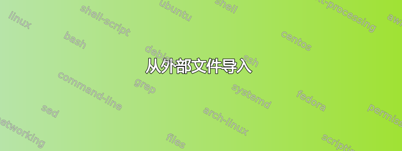
请注意,图形绘制库circular提供了自动布局(例如simple necklace layout),这意味着可以在没有特定坐标的情况下绘制所需的节点圆形排列,如第二张(蓝色)图所示(但请注意节点的顺序不同):
\documentclass[tikz,border=5]{standalone}
\usetikzlibrary{graphs,graphdrawing,arrows.meta}

\usegdlibrary{circular}
\tikzset{%
  edge 1/.style={>=Stealth},
  loop 1/.style={},
  loop 2/.style={loop above},
  loop 3/.style={loop below},
  loop 4/.style={loop left},
  loop 5/.style={loop right},
}
\def\luafiletomacro#1#2{%
  \edef#2{%
    \directlua{%
      file = io.open("#1", "r")
      data = file:read("*all")
      file:close()
      tex.print(data)
    }%
  }%
}
\tikzgraphsset{%
  n/.store in=\n,
  n = 1,
  adjacency matrix/.store in=\tikzadjacencymatrix,
  adjacency matrix from file/.code={\luafiletomacro{#1}{\tikzadjacencymatrix}},
  vertices/.store in=\tikzvertices,
  vertices={},
  vertices from file/.code={\luafiletomacro{#1}{\tikzvertices}},
  declare={adjacency graph}{[
    /utils/exec={\edef\adjacencygraph{%
      \directlua{%
         local i, j, n, v
         local vertices = {\tikzvertices}
         local matrix = {\tikzadjacencymatrix}
         local graph_spec = ""
         n = 0
         for i, vertex in pairs(vertices) do
            x = vertex[1]
            y = vertex[2]
            n = n + 1
            graph_spec = graph_spec .. " " .. n ..
              "[at={(" .. x .. "," .. y .. ")}];"
         end
         if n == 0 then
           n = \n\space
           for i = 1,n do
              if i > 1 then
                graph_spec = graph_spec .. ","
              end
              graph_spec = graph_spec .. " " .. i
           end
         end
         graph_spec = graph_spec .. ";"
         for i = 1,n do
           for j = 1,i do
             v = matrix[i][j]
             if v > 0 then
               if i == j then
                 graph_spec = graph_spec .. " " .. i ..
                   " ->[/tikz/loop " .. v .. "/.try]" .. i .. "; "
               else
                 if matrix[j][i] == 1 then
                   graph_spec = graph_spec .. " " .. i ..
                     " <->[/tikz/edge " .. v .. "/.try]" .. j .. "; "
                 else
                   graph_spec = graph_spec .. " " .. i ..
                     " ->[/tikz/edge " .. v .. "/.try]" .. j .. "; "
                 end
               end
             end
           end
         end
         tex.print(graph_spec)
      }%
    }},
    parse/.expand once=\adjacencygraph
  ]}%
}
\begin{document}
\begin{tikzpicture}[x=2cm,y=2cm]
\graph [nodes={circle, draw}, no placement] {

   adjacency graph[
     vertices={{0.809,0.588},{0.309,0.951},{-0.309,0.951},{-0.809,0.588},
       {-1.,0.},{-0.809,-0.588},{-0.309,-0.951},{0.309,-0.951},
       {0.809,-0.588},{1.,0.}},
     adjacency matrix={%
      {0,1,0,0,1,0,1,0,0,1},
      {1,0,1,0,0,1,0,1,0,0},
      {0,1,0,1,0,0,1,0,1,0},
      {0,0,1,0,1,0,0,1,0,1},
      {1,0,0,1,0,1,0,0,1,0},
      {0,1,0,0,1,0,1,0,0,1},
      {1,0,1,0,0,1,0,1,0,0},
      {0,1,0,1,0,0,1,0,1,0},
      {0,0,1,0,1,0,0,1,0,1},
      {1,0,0,1,0,1,0,0,1,0}
     }];
};

\tikzset{shift=(270:2), edge 1/.style={draw=blue}}
\graph [nodes={circle, draw}, simple necklace layout, node distance=1.25cm] {

    adjacency graph[n=10,
      adjacency matrix={%
       {0,1,0,0,1,0,1,0,0,1},{1,0,1,0,0,1,0,1,0,0},{0,1,0,1,0,0,1,0,1,0},
       {0,0,1,0,1,0,0,1,0,1},{1,0,0,1,0,1,0,0,1,0},{0,1,0,0,1,0,1,0,0,1},
       {1,0,1,0,0,1,0,1,0,0},{0,1,0,1,0,0,1,0,1,0},{0,0,1,0,1,0,0,1,0,1},
       {1,0,0,1,0,1,0,0,1,0}
      }];
 };

\end{tikzpicture}

\end{document}
