

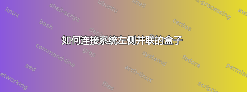
我想连接系统左侧的盒子,该盒子由一条线划分为 CPU 侧和 RF 链部分。此外,我想减少 (HT)^+ 和 T 盒之间的两条最外层连接线,以显示数据在系统中被压缩。为了清楚起见,我想将两个 (HT)^+ 盒连接成一个大盒子,2 个 xhat 盒也是如此。
\documentclass[tikz,border=2mm]{standalone}

\usepackage{tikz} % Create graphics in Latex
\usepackage{circuitikz}

\begin{document}

\begin{tikzpicture}[block/.style={draw, minimum height=2cm, minimum width=5mm}]

  \node[block, font=\boldmath] at (0,0) (x) {$\hat{x}$};
  \node[block, font=\boldmath] at (1.5,0) (ht) {$(HT)^+$};
  \node[block, font=\boldmath] at (5.5,0) (t) {$T$};
  \node[block, font=\boldmath] at (6.5,0) (y) {$Y$};
  \node[block, font=\bfseries] at (8,0) (adc) {ADC};
  \foreach \y in {-0.25, -0.75, 0.25, 0.75}{
    \draw [black, -] ([yshift=\y cm]x.west)--++(180:1cm);
    \foreach \i [remember=\i as \lasti (initially x)] in {ht,t,y,adc}
        \draw [black, -] ([yshift=\y cm]\lasti.east)--([yshift=\y cm]\i.west);
  }

  \draw[black, -] ([yshift=0.75cm]adc.east)--++(0:.5cm) node[antenna] {};
  \draw[black, -] ([yshift=0.25cm]adc.east)--++(0:1.25cm) node[antenna] {};
  \draw[black, -] ([yshift=-0.25cm]adc.east)--++(0:2cm) node[antenna] {};
  \draw[black, -] ([yshift=-0.75cm]adc.east)--++(0:2.75cm) node[antenna] {};
  \draw[densely dotted] (3.75,2) -- (3.75,-7);
  \node[draw] at (2,2) {CPU};
  \node[draw] at (6,2) {RF-chain};

  \node[block, font=\boldmath] at (0,-5) (x) {$\hat{x}$};
  \node[block, font=\boldmath] at (1.5,-5) (ht) {$(HT)^+$};
  \node[block, font=\boldmath] at (5.5,-5) (t) {$T$};
  \node[block, font=\boldmath] at (6.5,-5) (y) {$Y$};
  \node[block, font=\bfseries] at (8,-5) (adc) {ADC};
  \foreach \y in {-0.25, -0.75, 0.25, 0.75}{
    \draw [black, -] ([yshift=\y cm]x.west)--++(180:1cm);
    \foreach \i [remember=\i as \lasti (initially x)] in {ht,t,y,adc}
        \draw [black, -] ([yshift=\y cm]\lasti.east)--([yshift=\y cm]\i.west);
  }

  \draw[black, -] ([yshift=0.75cm]adc.east)--++(0:.5cm) node[antenna] {};
  \draw[black, -] ([yshift=0.25cm]adc.east)--++(0:1.25cm) node[antenna] {};
  \draw[black, -] ([yshift=-0.25cm]adc.east)--++(0:2cm) node[antenna] {};
  \draw[black, -] ([yshift=-0.75cm]adc.east)--++(0:2.75cm) node[antenna] {};
  \node[draw] at (2,2) {CPU};
  \node[draw] at (6,2) {RF-chain};

  \end{tikzpicture}
\end{document}
答案1
编辑(2): 根据收到的评论,我现在想象了三种可能的线路分组和天线数量解决方案:
- 8条输入线,块
x和之间有4条线HT,其他块只有两条线和两根天线 - 2 x 4 输入线,
x和之间有 2 x 2 线HT,其他块只有两条线和两个天线 - 8条输入线,块
x和之间有4条线HT,其他块只有2条线和4根天线
两种可能性如下所示。我仍然不清楚每个 ADC 块是否连接两个或四个天线。暂时假设只有两个,但是还添加了四个天线的解决方案
代码进一步缩短,添加了 tikz 库chains,删除了所有绝对坐标,因此节点之间的距离由 控制node distance。所有线条的绘制都合并在重嵌套foreach循环中
版本 1:

版本 2:

版本 3:

\documentclass[tikz,border=2mm]{standalone}
\usepackage{circuitikz}

\usetikzlibrary{chains,fit,positioning}

    \begin{document}
% version 1
\begin{tikzpicture}[
node distance = 16mm and 5mm,
  start chain = going right,
 block/.style = {draw, minimum height=20mm, minimum width=5mm,
                 font=\boldmath,on chain}]
% upper blocks
\node (x1)    [block,draw=none]             {};
\node (ht1)   [block,draw=none]             {\hphantom{$\boldmath(HT)^+$}};
\node (t1)    [block,right=22mm of ht1]     {$T$};
\node (y1)    [block]                       {$Y$};
\node (adc1)  [block]                       {ADC};
% lower blocks
\node (x2)    [block,draw=none,below=of x1] {};
\node (ht2)   [block,draw=none]             {\hphantom{$\boldmath(HT)^+$}};
\node (t2)    [block,right=22mm of ht2]     {$T$};
\node (y2)    [block]                       {$Y$};
\node (adc2)  [block]                       {ADC};
% common input nodes
\node (in1)   [draw,inner sep=0pt, fit= (x1)  (x2), label=center:$\boldmath\hat{x}$] {};
\node (in2)   [draw,inner sep=0pt, fit=(ht1)  (ht2),label=center:$\boldmath(HT)^+$] {};
% top blocks
    \node (cpu) [above=5mm of in2]     {CPU};
    \node (rf)  [above=5mm of y1]      {RF-chain};
\draw[densely dotted] ([xshift=11mm] cpu.north -| in2.east) coordinate (in3)
                    -- (in3 |- in2.south);
% lines between blocks
    \foreach \y in {-0.75, -0.25, 0.25, 0.75}
{
% 8 input lines
    \draw   ([yshift=\y cm +1 cm] in1.west)--++(180:1cm);
    \draw   ([yshift=\y cm -1 cm] in1.west)--++(180:1cm);
% 4 lines between x and HT
    \draw   ([yshift=\y cm] in2.west) -- ([yshift=\y cm] in1.east |- in2.west);
}
% 2 lines between other blocks
    \foreach \j in {1, 2}
{
        \foreach \y  in {-0.25, 0.25}
    {
            \foreach \i [remember=\i as \lasti (initially ht\j)] in {t\j,y\j,adc\j}
    \draw ([yshift=  \y cm]\lasti.east)--([yshift=\y cm]\i.west);
    \draw ([yshift=1-\y cm] adc\j.east)--++(0:1+1.5*\y)   node[antenna] {};
    }
}
\end{tikzpicture}

% version 2
\begin{tikzpicture}[
node distance = 16mm and 5mm,
  start chain = going right,
 block/.style = {draw, minimum height=20mm, minimum width=5mm,
                 font=\boldmath,on chain}]
% upper blocks
\node (x1)    [block,draw=none]             {};
\node (ht1)   [block,draw=none]             {\hphantom{$\boldmath(HT)^+$}};
\node (t1)    [block,right=22mm of ht1]     {$T$};
\node (y1)    [block]                       {$Y$};
\node (adc1)  [block]                       {ADC};
% lower blocks
\node (x2)    [block,draw=none,below=of x1] {};
\node (ht2)   [block,draw=none]             {\hphantom{$\boldmath(HT)^+$}};
\node (t2)    [block,right=22mm of ht2]     {$T$};
\node (y2)    [block]                       {$Y$};
\node (adc2)  [block]                       {ADC};
% common input nodes
\node (in1)   [draw,inner sep=0pt, fit= (x1)  (x2), label=center:$\boldmath\hat{x}$] {};
\node (in2)   [draw,inner sep=0pt, fit=(ht1)  (ht2),label=center:$\boldmath(HT)^+$]  {};
% top blocks
    \node (cpu) [above=5mm of in2]     {CPU};
    \node (rf)  [above=5mm of y1]      {RF-chain};
\draw[densely dotted] ([xshift=11mm] cpu.north -| in2.east) coordinate (in3)
                    -- (in3 |- in2.south);
% lines between blocks
    \foreach \y in {-0.75, -0.25, 0.25, 0.75}
{
% 8 input lines
    \draw   ([yshift=\y cm] x1.west)--++(180:1cm);
    \draw   ([yshift=\y cm] x2.west)--++(180:1cm);
}
% 2 lines between other blocks
    \foreach \j in {1, 2}
{
        \foreach \y  in {-0.25, 0.25}
    {
            \foreach \i [remember=\i as \lasti (initially x\j)] in {ht\j,t\j,y\j,adc\j}
    \draw ([yshift=  \y cm]\lasti.east)--([yshift=\y cm]\i.west);
    \draw ([yshift=1-\y cm] adc\j.east)--++(0:1+1.5*\y)   node[antenna] {};
    }
}
  \end{tikzpicture}

% Version 3
\begin{tikzpicture}[
node distance = 20mm and 5mm,
  start chain = going right,
 block/.style = {draw, minimum height=20mm, minimum width=5mm,
                 font=\boldmath,on chain}]
% upper blocks
\node (x1)    [block,draw=none]             {};
\node (ht1)   [block,draw=none]             {\hphantom{$\boldmath(HT)^+$}};
\node (t1)    [block,right=22mm of ht1]     {$T$};
\node (y1)    [block]                       {$Y$};
\node (adc1)  [block]                       {ADC};
% lower blocks
\node (x2)    [block,draw=none,below=of x1] {};
\node (ht2)   [block,draw=none]             {\hphantom{$\boldmath(HT)^+$}};
\node (t2)    [block,right=22mm of ht2]     {$T$};
\node (y2)    [block]                       {$Y$};
\node (adc2)  [block]                       {ADC};
% common input nodes
\node (in1)   [draw,inner sep=0pt, fit= (x1)  (x2), label=center:$\boldmath\hat{x}$] {};
\node (in2)   [draw,inner sep=0pt, fit=(ht1)  (ht2),label=center:$\boldmath(HT)^+$] {};
% top blocks
    \node (cpu) [above=5mm of in2]     {CPU};
    \node (rf)  [above=5mm of y1]      {RF-chain};
\draw[densely dotted] ([xshift=11mm] cpu.north -| in2.east) coordinate (in3)
                    -- (in3 |- in2.south);
% lines between blocks
    \foreach \y in {-0.75, -0.25, 0.25, 0.75}
{
% 8 input lines
    \draw   ([yshift=\y cm +1 cm] in1.west)--++(180:1cm);
    \draw   ([yshift=\y cm -1 cm] in1.west)--++(180:1cm);
% 4 lines between x and HT
    \draw   ([yshift=\y cm] in2.west) -- ([yshift=\y cm] in1.east |- in2.west);
}
% 2 lines between other blocks
    \foreach \j in {1, 2}
{
        \foreach \y  in {-0.25, 0.25}
    {
            \foreach \i [remember=\i as \lasti (initially ht\j)] in {t\j,y\j,adc\j}
    \draw ([yshift=  \y cm]\lasti.east)--([yshift=\y cm]\i.west);
    \draw ([yshift= 0.5 cm -\y cm] adc\j.east)--++(0:1+1.5*\y)   node[antenna] {};
    \draw ([yshift=-0.5 cm -\y cm] adc\j.east)--++([xshift=1.5cm] 0:1+1.5*\y)   node[antenna] {};
    }
}
\end{tikzpicture}
    \end{document}
现在应该很容易制作具有不同数量的线路和天线的新版本。我希望如此。