

我想在下tikz图中重现 我尝试使用命令
\matrix[nodes = {draw,ultra thick},row sep=0.2cm,column sep=0.2cm{

\node[rectangle] {};
...

};
然而我得到的东西并不真正适合我的要求。
评论更新后:我到目前为止所做的(远非我想要的)是
\documentclass{standalone}
\usepackage{tikz}
\usetikzlibrary{shapes,snakes}
\usepackage{verbatim}

\begin{document}


\begin{tikzpicture}[scale=3]
 \tikzstyle{ann} = [draw=none,fill=none,right]
 \matrix[nodes={draw, ultra thick, color=blue},
    row sep=0.2cm,column sep=0.2cm] {
 \node[rectangle] {}; &
 \node[rectangle] {}; &
 \node[rectangle] {};&
 \node[rectangle] {};\\
 \node[rectangle] {}; &
 \node[rectangle] {}; &
 \node[rectangle] {};&
 \node[rectangle] {};\\
 \node[rectangle] {}; &
 \node[rectangle] {}; &
 \node[rectangle] {};&
 \node[rectangle] {};\\
 \node[rectangle] {}; &
 \node[rectangle] {}; &
 \node[rectangle] {};&
 \node[rectangle] {};\\    };
\end{tikzpicture}


\end{document}
答案1
通过使用matrix和相当复杂的节点定义,我设法获得:

\documentclass[tikz, margin=3mm]{standalone}
\usetikzlibrary{calc, matrix}
\makeatletter
 \def\tikzsavelastnodename#1{\let#1=\tikz@last@fig@name}
\makeatother

\begin{document}
    \begin{tikzpicture}%
  \tikzset{
add text/.style args = {#1:#2}{
        append after command={node[inner sep=2mm, font=\footnotesize\sffamily,
                                   anchor=#1]
        at (\tikzsavednodename.#1) {#2}}
                                },
add left text/.style args = {#1:#2}{
        append after command={node[inner sep=0pt, font=\footnotesize\sffamily,
                rotate around={+90:($(+2mm,2mm)+(\tikzsavednodename.#1)$)}]
        at (\tikzsavednodename.#1) {#2}}
                                },
add right text/.style args = {#1:#2}{
        append after command={node[inner sep=0pt, font=\footnotesize\sffamily,
                rotate around={-90:($(-2mm,2mm)+(\tikzsavednodename.#1)$)}]
        at (\tikzsavednodename.#1) {#2}}
                                },
saveLNN/.style = {append after command={%
        \pgfextra{\tikzsavelastnodename\tikzsavednodename}},#1},
MN/.style args = {#1/#2}{% Matrix Nodes
    draw, rounded corners=5mm, ultra thick, color=#1,
    minimum size=32mm, outer sep=1mm,
    font=\fontsize{32}{16}\bfseries\color{#1}\selectfont,
    align=center,
    node contents={#2\\[\baselineskip]~},
    saveLNN},
           }

    \matrix[matrix of nodes,
%            ampersand replacement=\&,
            row sep=1mm,column sep=1mm]
{
 \node[MN=cyan/ISTJ,
       add text=north: text below top,
       add text=south: text above bottom,
       add left text =west: rotated text left,
       add right text=east: rotated text right
       ];   &
 \node[MN=cyan/ISFJ,
       add text=north: text below top,
       add text=south: text above bottom,
       add left text =west: rotated text left,
       add right text=east: rotated text right
       ];   \\
};
    \end{tikzpicture}
\end{document}
我并不关心节点边界处的实际文本,也不关心节点大小(我不建议使用scale,更好的是更改minim um size和调整所用字体的大小)。
MWE 确实很小,在矩阵中我只考虑两个单元。其他您可以按照显示的方式添加。
附录: 第一个解决方案没有必要那么复杂(基于我的一个旧的通用解决方案),因此对于这种所有节点中侧边文本的锚点都相同的情况,上述解决方案可以大大简化:
\documentclass[tikz, margin=3mm]{standalone}
\usepackage{tikz}
\usetikzlibrary{calc, matrix}

\newcommand\ppbb{path picture bounding box}

\begin{document}
    \begin{tikzpicture}[
ST/.style = {font=\footnotesize\sffamily, text=#1},
MN/.style args = {#1/% color
                  #2/% main text
                  #3/% top text
                  #4/% bottom text
                  #5/% left text
                  #6%
                  }{% Matrix Nodes
    draw =#1, rounded corners=5mm, line width=1mm,
    minimum size=32mm, outer sep=1mm,
    font=\fontsize{32}{16}\bfseries\color{#1}\selectfont,
    align=center,
    node contents={#2\\[\baselineskip]~},
    path picture={%
    \node[ST=#1,yshift=-3mm] at (\ppbb.north)  {#3};
    \node[ST=#1,yshift=+2mm] at (\ppbb.south)  {#4};
    \node[ST=#1,rotate around={+90:($(+1.5mm,1.5mm)+(\ppbb.west)$)}]
          at (\ppbb.west) {#5};
    \node[ST=#1,rotate around={-90:($(-1.5mm,1.5mm)+(\ppbb.east)$)}]
          at (\ppbb.east) {#6};
                    }%  end path picture
                    }%% end of MN
                        ]
\matrix[matrix of nodes,
            row sep=0.1mm, column sep=0.1mm]
{
\node[MN=cyan/ISTJ/text below top/text above bottom%
        /rotated text left/rotated text right];
    &
\node[MN=purple/ISFJ/text below top/text above bottom%
        /rotated text left/rotated text right];    \\
};
    \end{tikzpicture}
\end{document}
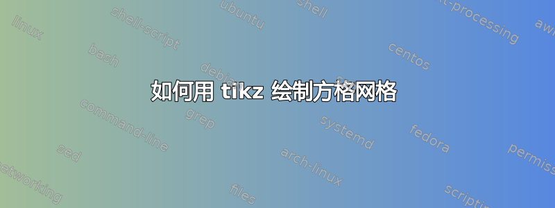
在此解决方案中,使用了侧边文本的锚点path picture bounding box。新代码(确定更粗的节点边框和彩色的侧边文本)的结果为:

答案2
我只是想完成对 Zarko 答案的评论。以下代码使用了 Zarko 的代码,但节点中的所有文本都使用方便labels的放置anchors。
\documentclass[tikz, margin=3mm]{standalone}
\usepackage{tikz}
\usetikzlibrary{matrix}

\begin{document}
    \begin{tikzpicture}[
        ST/.style = {font=\footnotesize\sffamily, text=#1},
        MN/.style args = {%
            #1/% color
            #2/% main text
            #3/% top text
            #4/% bottom text
            #5/% left text
            #6%  right text
        }{% Matrix Nodes
            draw =#1, rounded corners=5mm, line width=1mm,
            minimum size=32mm, outer sep=1mm,
            align=center,
            label={[above=7mm, text=#1, font=\fontsize{32}{16}\bfseries\selectfont]center:#2},
            label={[ST=#1, anchor=north, below=1mm]north:#3},
            label={[ST=#1, anchor=south, above=1mm]south:#4},
            label={[ST=#1, rotate=90, anchor=north, below=1mm]west:#5},
            label={[ST=#1, rotate=270, anchor=north, below=1mm]east:#6},
        },%% end of MN
        MN/.default={cyan/ISTJ/text below top/text above bottom/rotated text left/rotated text right},
]

\matrix[row sep=1pt, column sep=1pt]{
\node[MN]{};
&
\node[MN=red/ISFJ/text below top/text above bottom/rotated text left/rotated text right]{};
\\};
\end{tikzpicture}
\end{document}
