

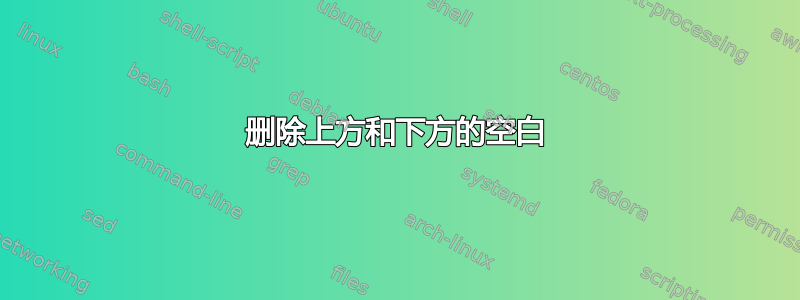
我有一个 TikZ 图形代码,但是当我生成 pdf 文件时,图形上方和下方有一些空白,我想删除这些空白。我尝试使用该\clip命令,但我不知道如何使用它(实际上我不知道以某种方式放置矩形坐标以删除不需要的空间)。
这是我的 LaTeX 代码:
%\makeatletter\let\ifGm@compatii\relax\makeatother
%\useoutertheme{split}

\makeatletter\let\ifGm@compatii\relax\makeatother
\documentclass[11pt]{beamer}
%
\usepackage{times}
\usepackage[english]{babel}
\usepackage{pgf,pgfarrows,pgfnodes,pgfautomata,pgfheaps}
\usepackage{amsmath,amssymb}
\usepackage[latin1]{inputenc}
\usepackage{geometry}
\usepackage{tikz}

\usepackage{lmodern}

\usetikzlibrary{decorations.pathmorphing}
\usetikzlibrary{shapes}
\tikzset{snake it/.style={decorate, decoration=snake}}

%\setcounter{MaxMatrixCols}{10}
\tikzset{cross/.style={cross out, draw,
         minimum size=2*(#1-\pgflinewidth),
         inner sep=0pt, outer sep=0pt}}
\usetikzlibrary{arrows}
\setbeamertemplate{navigation symbols}{}
\tikzset{
LL/.style={
  draw=black,decorate,
  decoration={snake, segment length=3mm, amplitude=1mm,post length=2mm}
  }
}
\begin{document}
%\pagestyle{empty}
%\tikzstyle{int}=[draw, fill=blue!20] \tikzstyle{sous}=[node
%§distance=2.45cm]
% \tikzstyle{init} = [draw,fill=red!20]
\tikzset{->-/.style={decoration={
  markings,
  mark=at position #1 with {\arrow{>}}},postaction={decorate}}}

\begin{figure}
\centering
\begin{tikzpicture}%[auto,>=latex']

  \draw[draw=black, snake it] (12cm,5cm) ;

  \draw (-2.8,-0.8) -- (-1.5,-0.8) -- (-1.5,0.8) -- (-2.8,0.8) -- (-2.8,-0.8); %% Transmitter
  % \draw (-1.1,0.4) -- (6.8,0.4) ; %%line 1
  \draw (-1.04,-0.4) -- (1.35,-0.4) ; %% line 2 1st segment
  \draw (1.65,-0.4) -- (5.55,-0.4); %% line 2 contin.
  \draw (6.8,-0.8) -- (8.1,-0.8) -- (8.1,0.8) -- (6.8,0.8) -- (6.8,-0.8); %% Receiver
    \draw[black, thick] (-1.3,-0.2) -- (-1,-0.2) -- (-1.15,-0.5) -- (-1.3,-0.2); % triangle 1
   \draw[black, thick] (5.8,-0.2) -- (5.5,-0.2) -- (5.65,-0.5) -- (5.8,-0.2);  % triangle 2
   \draw[black, thick] (-1.5,-0.65) -- (-1.15,-0.65) -- (-1.15,-0.5) ;% antenna 1 support
      \draw[black, thick] (6.8,-0.65) -- (6.4,-0.65) ;% antenna 2 support
      \draw[black, thick] (6.1,-0.65) -- (5.65,-0.65) -- (5.65,-0.5);% antenna 2 support (2)
      \draw[black, thick]  (6.25,-0.65) circle (0.15); %% AWGN
       \draw (1.5,-0.4) circle (0.15); %% fading
   \draw[black, thick] (6.25,-0.65) node[cross=3.4pt,rotate=45,black]{}; %%  + sign
\draw (1.5,-0.4) node[cross=3.6pt,rotate=0,black]{}; %% x sign

\draw[black, thick] (-1.2,0.7) -- (-0.5,0.7) -- (-0.5,0.4) -- (-1.2,0.4) -- (-1.2,0.7); %% FSO1
\draw[black, thick]  (2.8,1.05) -- (4.9,1.05) -- (4.9,0.05) -- (2.8,0.05) -- (2.8,1.05); %% optical receiver
\draw[black, thick]  (-1.2,0.7) -- (-1.3,0.7) -- (-1.3,0.1) -- (-1.5,0.1) -- (-1.5,0.0)-- (-1.2,0.0) -- (-1.2,0.7); %% FSO2 support


\path[LL,thick]      (-0.4,0.55) -- (0.9,0.55); %% wave 1
\path[LL,thick,->,>=latex]  (1.2,0.55) -- (2.8,0.55); %% wave 1
%\draw[black, thick]  (3.6,0.8) -- (4.4,0.8) -- (4.4,0.3) -- (3.6,0.3) -- (3.6,0.8); %% photodet.
 %\draw (2.45,-0.4) -- (5.55,-0.4); %% line between phot. & Amplif.
  % \draw[black, thick] (4.8,0.8) -- (5.35,0.55) -- (4.8,0.3) -- (4.8,0.8);  % Amplif.
   \draw (6.25,0.55) circle (0.15); %% AWGN2
     \draw (6.25,0.55) node[cross=3.4pt,rotate=45,black]{}; %%  + sign (2)
     %\draw (3.1,0.55) -- (3.6,0.55); %% line between FSO2. & PD.
     \draw (4.9,0.55) -- (6.1,0.55); %% line between PD & AWGN2
     \draw (5.35,0.55) -- (6.1,0.55); %% line between Amp & AWGN2
     \draw (6.4,0.55) -- (6.8,0.55); %% line between AWGN & MRC

     \draw[->] (1.5,-0.85) -- (1.5,-0.55); %% fading arrow
     \draw[->] (6.25,-1.1) -- (6.25,-0.8); %% AWGN1 arrow
     \draw[->] (6.25,1.0) -- (6.25,0.7); %% AWGN2 arrow

            \draw (1.05,0.55) circle (0.15); %% irradiance
            \draw[->] (1.05,1.0) -- (1.05,0.7); %% irradiance arrow
\draw (1.05,0.55) node[cross=3.6pt,rotate=0,black]{}; %% x sign
\node[font=\fontsize{8}{8}\selectfont,align=center] at (7.45,0) {MRC \\ Combiner};
\node[font=\fontsize{8}{8}\selectfont,align=center] at (-0.95,1.2) {FSO Laser\\Device};
\node[font=\fontsize{8}{8}\selectfont,align=center] at (3.83,0.60) {Optical Receiver};
\node[font=\fontsize{7}{7}\selectfont,align=center,align=center] at (1.22,1.25) {(Irradiance)\\$I=I_lI_aI_p$};
\node[font=\fontsize{7}{7}\selectfont,align=center,align=center] at (1.5,-0.97) {$\alpha_2$}; %% fading alpha2
\node[font=\fontsize{7}{7}\selectfont,align=center,align=center] at (6.25,1.3) {$n\sim(0,\frac{N_0}{2})$}; %% noise1
\node[font=\fontsize{7}{7}\selectfont,align=center,align=center] at (6.25,-1.3) {$n'\sim(0,\frac{N_0}{2})$}; %% noise2
\node[font=\fontsize{8}{8}\selectfont,align=center,align=center] at (-1.57,1.75) {Transmitter};
\node[font=\fontsize{8}{8}\selectfont,align=center,align=center] at (1.25,1.75) {Channel};
\node[font=\fontsize{8}{8}\selectfont,align=center,align=center] at (5.5,1.75) {Receiver};
%\node[text width=0.8cm,align=center] at (7.4,0) {MRC \\ Combiner};
%\node[text width=0.8cm,align=center] at (7.4,0) {MRC \\ Combiner};
 \draw[dashed] (0.1,1.6) -- (-3.1,1.6) -- (-3.1,-1.5) -- (0.1,-1.5) -- (0.1,1.6); %% Transmitter dashed box
\draw[dashed] (0.3,1.6) -- (1.99,1.6) -- (1.99,-1.5) -- (0.3,-1.5) -- (0.3,1.6); %% channel dashed box
\draw[dashed] (2.5,1.6) -- (8.5,1.6) -- (8.5,-1.5) -- (2.5,-1.5) -- (2.5,1.6); %% channel dashed box
\clip (-3,3) rectangle (9,-3);
\end{tikzpicture}%}
\end{figure}
\end{document}
答案1
有几种可能性。您可以注释掉 -line snake。您可以剪切(参见上面的注释)不需要的空白(请尝试边框,您就会明白它们的含义)。另一个解决方案可能是使用 -environment pgfinterruptboundingbox(请查看手册以了解这方面的说明)。
%\makeatletter\let\ifGm@compatii\relax\makeatother
%\useoutertheme{split}

\makeatletter\let\ifGm@compatii\relax\makeatother
\documentclass[11pt]{beamer}
%
\usepackage{times}
\usepackage[english]{babel}
\usepackage{pgf,pgfarrows,pgfnodes,pgfautomata,pgfheaps}
\usepackage{amsmath,amssymb}
\usepackage[latin1]{inputenc}
\usepackage{geometry}
\usepackage{tikz}

\usepackage{lmodern}

\usetikzlibrary{decorations.pathmorphing}
\usetikzlibrary{shapes}
\tikzset{snake it/.style={decorate, decoration=snake}}

%\setcounter{MaxMatrixCols}{10}
\tikzset{cross/.style={cross out, draw,
         minimum size=2*(#1-\pgflinewidth),
         inner sep=0pt, outer sep=0pt}}
\usetikzlibrary{arrows}
\setbeamertemplate{navigation symbols}{} \tikzset{ LL/.style={
  draw=black,decorate,
  decoration={snake, segment length=3mm, amplitude=1mm,post length=2mm}
  }
}
\begin{document}
%\pagestyle{empty}
%\tikzstyle{int}=[draw, fill=blue!20] \tikzstyle{sous}=[node
%§distance=2.45cm]
% \tikzstyle{init} = [draw,fill=red!20]
\tikzset{->-/.style={decoration={
  markings,
  mark=at position #1 with {\arrow{>}}},postaction={decorate}}}

\begin{figure}
\centering
\begin{tikzpicture}%[auto,>=latex']

%  \draw[draw=black, snake it] (12cm,5cm) ;

  \clip (-3,3) rectangle (9,-3);

  \draw (-2.8,-0.8) -- (-1.5,-0.8) -- (-1.5,0.8) -- (-2.8,0.8) -- (-2.8,-0.8); %% Transmitter
  % \draw (-1.1,0.4) -- (6.8,0.4) ; %%line 1
  \draw (-1.04,-0.4) -- (1.35,-0.4) ; %% line 2 1st segment
  \draw (1.65,-0.4) -- (5.55,-0.4); %% line 2 contin.
  \draw (6.8,-0.8) -- (8.1,-0.8) -- (8.1,0.8) -- (6.8,0.8) -- (6.8,-0.8); %% Receiver
    \draw[black, thick] (-1.3,-0.2) -- (-1,-0.2) -- (-1.15,-0.5) -- (-1.3,-0.2); % triangle 1
   \draw[black, thick] (5.8,-0.2) -- (5.5,-0.2) -- (5.65,-0.5) -- (5.8,-0.2);  % triangle 2
   \draw[black, thick] (-1.5,-0.65) -- (-1.15,-0.65) -- (-1.15,-0.5) ;% antenna 1 support
      \draw[black, thick] (6.8,-0.65) -- (6.4,-0.65) ;% antenna 2 support
      \draw[black, thick] (6.1,-0.65) -- (5.65,-0.65) -- (5.65,-0.5);% antenna 2 support (2)
      \draw[black, thick]  (6.25,-0.65) circle (0.15); %% AWGN
       \draw (1.5,-0.4) circle (0.15); %% fading
   \draw[black, thick] (6.25,-0.65) node[cross=3.4pt,rotate=45,black]{}; %%  + sign
\draw (1.5,-0.4) node[cross=3.6pt,rotate=0,black]{}; %% x sign

\draw[black, thick] (-1.2,0.7) -- (-0.5,0.7) -- (-0.5,0.4) -- (-1.2,0.4) -- (-1.2,0.7); %% FSO1
\draw[black, thick]  (2.8,1.05) -- (4.9,1.05) -- (4.9,0.05) -- (2.8,0.05) -- (2.8,1.05); %% optical receiver
\draw[black, thick]  (-1.2,0.7) -- (-1.3,0.7) -- (-1.3,0.1) -- (-1.5,0.1) -- (-1.5,0.0)-- (-1.2,0.0) -- (-1.2,0.7); %% FSO2 support


\path[LL,thick]      (-0.4,0.55) -- (0.9,0.55); %% wave 1
\path[LL,thick,->,>=latex]  (1.2,0.55) -- (2.8,0.55); %% wave 1
%\draw[black, thick]  (3.6,0.8) -- (4.4,0.8) -- (4.4,0.3) -- (3.6,0.3) -- (3.6,0.8); %% photodet.
 %\draw (2.45,-0.4) -- (5.55,-0.4); %% line between phot. & Amplif.
  % \draw[black, thick] (4.8,0.8) -- (5.35,0.55) -- (4.8,0.3) -- (4.8,0.8);  % Amplif.
   \draw (6.25,0.55) circle (0.15); %% AWGN2
     \draw (6.25,0.55) node[cross=3.4pt,rotate=45,black]{}; %%  + sign (2)
     %\draw (3.1,0.55) -- (3.6,0.55); %% line between FSO2. & PD.
     \draw (4.9,0.55) -- (6.1,0.55); %% line between PD & AWGN2
     \draw (5.35,0.55) -- (6.1,0.55); %% line between Amp & AWGN2
     \draw (6.4,0.55) -- (6.8,0.55); %% line between AWGN & MRC

     \draw[->] (1.5,-0.85) -- (1.5,-0.55); %% fading arrow
     \draw[->] (6.25,-1.1) -- (6.25,-0.8); %% AWGN1 arrow
     \draw[->] (6.25,1.0) -- (6.25,0.7); %% AWGN2 arrow

            \draw (1.05,0.55) circle (0.15); %% irradiance
            \draw[->] (1.05,1.0) -- (1.05,0.7); %% irradiance arrow
\draw (1.05,0.55) node[cross=3.6pt,rotate=0,black]{}; %% x sign
\node[font=\fontsize{8}{8}\selectfont,align=center] at (7.45,0) {MRC
\\ Combiner}; \node[font=\fontsize{8}{8}\selectfont,align=center] at
(-0.95,1.2) {FSO Laser\\Device};
\node[font=\fontsize{8}{8}\selectfont,align=center] at (3.83,0.60)
{Optical Receiver};
\node[font=\fontsize{7}{7}\selectfont,align=center,align=center] at
(1.22,1.25) {(Irradiance)\\$I=I_lI_aI_p$};
\node[font=\fontsize{7}{7}\selectfont,align=center,align=center] at (1.5,-0.97) {$\alpha_2$}; %% fading alpha2
\node[font=\fontsize{7}{7}\selectfont,align=center,align=center] at (6.25,1.3) {$n\sim(0,\frac{N_0}{2})$}; %% noise1
\node[font=\fontsize{7}{7}\selectfont,align=center,align=center] at (6.25,-1.3) {$n'\sim(0,\frac{N_0}{2})$}; %% noise2
\node[font=\fontsize{8}{8}\selectfont,align=center,align=center] at
(-1.57,1.75) {Transmitter};
\node[font=\fontsize{8}{8}\selectfont,align=center,align=center] at
(1.25,1.75) {Channel};
\node[font=\fontsize{8}{8}\selectfont,align=center,align=center] at
(5.5,1.75) {Receiver};
%\node[text width=0.8cm,align=center] at (7.4,0) {MRC \\ Combiner};
%\node[text width=0.8cm,align=center] at (7.4,0) {MRC \\ Combiner};
 \draw[dashed] (0.1,1.6) -- (-3.1,1.6) -- (-3.1,-1.5) -- (0.1,-1.5) -- (0.1,1.6); %% Transmitter dashed box
\draw[dashed] (0.3,1.6) -- (1.99,1.6) -- (1.99,-1.5) -- (0.3,-1.5) -- (0.3,1.6); %% channel dashed box
\draw[dashed] (2.5,1.6) -- (8.5,1.6) -- (8.5,-1.5) -- (2.5,-1.5) -- (2.5,1.6); %% channel dashed box
\clip (-3,3) rectangle (9,-3);
\end{tikzpicture}%}
\end{figure}
\end{document}