

以下是代码:
\documentclass {article}
\usepackage {tikz}
\usetikzlibrary {positioning}
\definecolor {turboviole}{cmyk}{0.70,0,0,0}

\begin {document}
\begin {center}
\begin {tikzpicture}[-latex ,auto ,node distance =4 cm and 5cm ,on grid ,
semithick ,
state/.style ={ circle ,top color =white , bottom color = turboviole!20 ,
draw,turboviole , text=blue , minimum width =1 cm}]

% Left branch
\node[state] (root) {$[5,4,6,2,9,1,7,3]$};
\node[state] (A) [below left=of root] {$[4,1,2,3]$};
\node[state] (B) [below left=of A] {$[2,1,3]$};
\node[state] (C) [below left=of B] {$[1]$};
\node[state] (D) [below right=of B] {$[3]$};

% Call paths
\path (root) edge [bend right =25] node [below left=0.15cm]
{$\textcolor{red}{Call 1},Pivot < 5$} (A);
\path (A) edge [bend right =25] node [below left =0.15 cm] {$\textcolor{red}
{Call 2}, Pivot <4$} (B);
\path (B) edge [bend right =25] node [below left =0.15 cm] {$\textcolor{red}
{Call 3}, Pivot <2$} (C);
\path (B) edge [bend left =25] node [below right=0.15 cm] {$\textcolor{red}
{Call 4}, Pivot >2$} (D);

% Returning paths
\path (C) edge [bend right =25] node [above right =0.15 cm {$\textcolor{green}{Return 1}$} (B);
\path (D) edge [bend left =25] node [above left =0.15 cm] {$\textcolor{green}{Return 2}$} (B);
\path (B) edge [bend right =25] node [above right =0.15 cm] {$\textcolor{green}{Return 3}$} (A);
\path (A) edge [bend right =25] node [above right =0.15 cm] {$\textcolor{green}{Return 4}$} (root);

% Right branch
\node[state] (E) [below right=of root] {$[6,9,7]$};
\node[state] (F) [below right=of E] {$[9,7]$};
\node[state] (G) [below right=of F] {$[7]$};

% Call Paths
\path (root) edge [bend left =25] node [below right=0.15cm] {$\textcolor{red}{Call 5}, Pivot > 5$} (E);
\path (E) edge [bend left =25] node [below right=0.15 cm] {$\textcolor{red}{Call 6}, Pivot >6$} (F);
\path (F) edge [bend left =25] node [below right=0.15 cm] {$\textcolor{red}{Call 7}, Pivot >9$} (G);

% Returning paths
% intentionally not included

\end{tikzpicture}
\end{center}
\end{document}
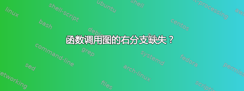
结果:

我希望您就以下方面提出建议和推荐:
图表缺失的右侧部分。我做错了什么?
改变颜色
edges以匹配文本颜色描述节点包含的内容:调用和返回。如何改变边缘的颜色?如何放置文本描述节点位于边缘上方,以便可见?
任何其他建设性的意见也将受到赞赏!
注:代码思路借鉴自这里。
答案1
回答标题中的问题:右侧部分没有缺失,只是您的图表太宽了,所以您看到的内容就像您插入了 25 厘米宽的图像一样——它会粘在右边距中并超出页面。一个简单的解决方法是设置node distance=3cm and 1cm,而不是4cm and 5cm您已有的 。
不过,在下面的代码中,我对此做了一些手动调整,以便更好地利用空间。
至于颜色,您可以使用edge[draw=red]使边变成红色,正如 cfr 在评论中所说。或者,由于您要在同一个 中添加箭头和节点path,因此您可以执行\path [red] ...。我在下面做了一个变体,其中我使用了scope环境 和every path/.append style={}。将整个节点变成红色,当然意味着Pivot N > 5也会变成红色,这可以用 来修复\color{black}。
代码还有其他变化,如果有任何不清楚的地方请询问。
(注意:图像中的框架来自包装showframe,仅用于显示图表比文本宽度窄。您需要删除包装showframe。)

\documentclass{article}
\usepackage{amsmath,showframe}
\usepackage{tikz}
\usetikzlibrary{positioning}
\definecolor{turboviole}{cmyk}{0.70,0,0,0}
\newcommand\callpivot[2]{Call #1,\\\color{black}$\text{Pivot #2} > 5$}
\begin{document}
\begin{center}
\begin{tikzpicture}[
   -latex,
   auto,
   node distance=3cm and 1cm,
   on grid,
   semithick,
   state/.style={
     circle,
     top color=white,
     bottom color=turboviole!20,
     draw,
     turboviole,
     text=blue,
     minimum width=1cm
   },
   call/.style={
     red,
     every node/.append style={align=center}
   },
   return/.style={green}
]

% Left branch
\node[state] (root) {$[5,4,6,2,9,1,7,3]$};
\node[state] (A) [below left=2cm and 3cm of root] {$[4,1,2,3]$};
\node[state] (B) [below left=3cm and 0cm of A] {$[2,1,3]$};
\node[state] (C) [below left=3cm and 2cm of B] {$[1]$};
\node[state] (D) [below right=3and 2cm of B] {$[3]$};

% Call paths
\begin{scope}[every path/.append style={call}]
\path (root) edge [bend right=25] node [above left]  {\callpivot{1}{5}} (A);
\path (A) edge [bend right=25] node [left] {\callpivot{2}{4}} (B);
\path (B) edge [bend right=25] node [above left] {\callpivot{3}{2}} (C);
\path (B) edge [bend left=25] node [above right] {\callpivot{4},{2}} (D);
\end{scope}

% Returning paths
\begin{scope}[every path/.append style={return}]
\path (C) edge [bend right=15] node [right,pos=0.1] {Return 1} (B);
\path (D) edge [bend left=15] node [left,pos=0.4] {Return 2} (B);
\path (B) edge [bend right=25] node [right] {Return 3} (A);
\path (A) edge [bend right=25] node [below right] {Return 4} (root);
\end{scope}

% Right branch
\node[state] (E) [below right=2cm and 3cm of root] {$[6,9,7]$};
\node[state] (F) [below=of E] {$[9,7]$};
\node[state] (G) [below=of F] {$[7]$};

% Call Paths
\begin{scope}[every path/.append style={call}]
\path (root) edge [bend left=25] node [above right] {\callpivot{5}{5}} (E);
\path (E) edge [bend left=25] node [right] {\callpivot{6}{6}} (F);
\path (F) edge [bend left=25] node [right] {\callpivot{7}{9}} (G);
\end{scope}

% Returning paths
% intentionally not included

\end{tikzpicture}
\end{center}
\end{document}