

如果没有John Kormylo 制作的超酷宏和Torbjørn T. 的回答非常有帮助。我不可能走到这一步。我的最终目标是让使用 Ti 伪造 3D 球体变得更容易钾Z. 这已经很好了,但我想尝试一种不同的、可以说是更直接的方法来绘制相关对象。这是我的 MWE。
\documentclass{article}
\usepackage{tikz}
\usetikzlibrary{shadings}
% parametrizations from https://tex.stackexchange.com/a/410379/121799
\newcommand{\latitudearc}[4]{% #1=label (optional), #2=latitude
%#3 start angle #4 end angle
  \pgfextra{\pgfmathsetmacro{\RX}{\RadiusSphere*cos(#2)} % from https://tex.stackexchange.com/a/410567/121799
  \global\let\RX=\RX % from https://tex.stackexchange.com/a/352269/121799
  \pgfmathsetmacro{\RY}{\RX*sin(\Clat)}%
  \global\let\RY=\RY
  \pgfmathsetmacro{\CY}{\RadiusSphere*sin(#2)*cos(\Clat)}
  \global\let\CY=\CY
  \pgfmathsetmacro{\Xend}{\RX*cos(#4)}
  \global\let\Xend=\Xend
  \pgfmathsetmacro{\Yend}{\CY+\RY*sin(#4)}
  \global\let\Yend=\Yend}%
  plot [domain=#3:#4,smooth,#1] ({\RX*cos(\noexpand\x)},{\CY+\RY*sin(\noexpand\x)})
}
% compute ellipse rotation=\ROT, xradius=\RX, arc angle at equator=\LAT
\newcommand{\longitudearc}[4]{% #1=label (optional), #2=longitude
%#3 start angle #4 end angle
  \pgfextra{\pgfmathsetmacro{\ROT}{atan2(sin(\Clat)*sin(#2-\Clong),cos(#2-\Clong))}% alpha
  \global\let\ROT=\ROT
  \pgfmathsetmacro{\LAT}{asin(cos(\Clat)*cos(\ROT))}% north pole theta_n
  \global\let\LAT=\LAT
  \pgfmathsetmacro{\RX}{\RadiusSphere*tan(\LAT)*tan(\ROT)}% r_x
  \global\let\RX=\RX
  \pgfmathsetmacro{\DELTAX}{-90+\LAT}
  \global\let\DELTAX=\DELTAX
  \pgfmathsetmacro{\Xend}{\RX*cos(\ROT)*cos(#4+\DELTAX)-\RadiusSphere*sin(\ROT)*sin(#4+\DELTAX)}
  \global\let\Xend=\Xend
  \pgfmathsetmacro{\Yend}{\RadiusSphere*cos(\ROT)*sin(#4+\DELTAX)+\RX*sin(\ROT)*cos(#4+\DELTAX)}
  \global\let\Yend=\Yend
  }
  plot[domain=#3:#4,smooth,#1]({\RX*cos(\ROT)*cos(\noexpand\x+\DELTAX)-\RadiusSphere*sin(\ROT)*sin(\noexpand\x+\DELTAX)},
  {\RadiusSphere*cos(\ROT)*sin(\noexpand\x+\DELTAX)+\RX*sin(\ROT)*cos(\noexpand\x+\DELTAX)})
}
\newcommand{\hotspot}[3]{% #1=label (optional), #3=latitude, #2=longitude
  \pgfextra{\pgfmathsetmacro{\RX}{\RadiusSphere*cos(#3)} % from https://tex.stackexchange.com/a/410567/121799
  \global\let\RX=\RX % from https://tex.stackexchange.com/a/352269/121799
  \pgfmathsetmacro{\RY}{\RX*sin(\Clat)}%
  \global\let\RY=\RY
  \pgfmathsetmacro{\CY}{\RadiusSphere*sin(#3)*cos(\Clat)}
  \global\let\CY=\CY
  \pgfmathsetmacro{\Xloc}{\RX*cos(#2)}
  \global\let\Xloc=\Xloc
  \pgfmathsetmacro{\Yloc}{\CY+\RY*sin(#2)}
  \global\let\Yloc=\Yloc}%
}

\begin{document}

\begin{tikzpicture}
\def\RadiusSphere{4}% sphere radius
\def\Clat{20}% point of view latitude
\def\Clong{-90}% point of view longitude
\shade[ball color = gray!40, opacity = 0.5] (0,0) circle (\RadiusSphere);


\hotspot{0}{-120}{-40}
\filldraw (\Xloc,\Yloc) circle (0.2);
\hotspot{0}{-120}{30}
\filldraw (\Xloc,\Yloc) circle (0.2);
\hotspot{0}{-50}{-40}
\filldraw (\Xloc,\Yloc) circle (0.2);
\hotspot{0}{-50}{30}
\filldraw (\Xloc,\Yloc) circle (0.2);


\begin{scope}
\clip[variable=\x] \longitudearc{blue}{-120}{-40}{30}
%\pgfextra{\hotspot{0}{-50}{-40}} to  (\Xloc,\Yloc)  % <-NEEDED?
\latitudearc{blue}{30}{-120}{-50} %to ({\Xend},{\Yend})
%\pgfextra{\hotspot{0}{-120}{-40}} to  (\Xloc,\Yloc) % <-NEEDED?
\longitudearc{blue}{-50}{30}{-40} %to ({\Xend},{\Yend})
%\pgfextra{\hotspot{0}{-120}{30}} to  (\Xloc,\Yloc)  % <-NEEDED?
\latitudearc{blue}{-40}{-50}{-120} %to ({\Xend},{\Yend})
%\pgfextra{\hotspot{0}{-50}{30}} to  (\Xloc,\Yloc)  % <-NEEDED?
-- cycle;
\shade[ball color = blue!40, opacity = 0.5] (0,0) circle (\RadiusSphere);
\end{scope}
\end{tikzpicture}
\end{document}

这不是我想要的。但是,如果我取消注释底部\pgfextra的命令scope,即使用scope
\begin{scope}
\clip[variable=\x] \longitudearc{blue}{-120}{-40}{30}
\pgfextra{\hotspot{0}{-50}{-40}} to  (\Xloc,\Yloc)  % <-NEEDED?
\latitudearc{blue}{30}{-120}{-50} %to ({\Xend},{\Yend})
\pgfextra{\hotspot{0}{-120}{-40}} to  (\Xloc,\Yloc) % <-NEEDED?
\longitudearc{blue}{-50}{30}{-40} %to ({\Xend},{\Yend})
\pgfextra{\hotspot{0}{-120}{30}} to  (\Xloc,\Yloc)  % <-NEEDED?
\latitudearc{blue}{-40}{-50}{-120} %to ({\Xend},{\Yend})
\pgfextra{\hotspot{0}{-50}{30}} to  (\Xloc,\Yloc)  % <-NEEDED?
-- cycle;
\shade[ball color = blue!40, opacity = 0.5] (0,0) circle (\RadiusSphere);
\end{scope}
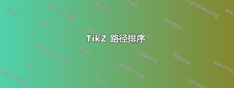
相反,我得到:

这几乎就是我想要的。(上下边界不正确。)也就是说,通过人为地将点插入路径,我可以得到由图限定的形状。在上图中,Ti钾出于某种原因,Z 总是通过返回起点来“完成”各个情节。现在我的问题是,是否有办法关闭它。
编辑:这是一个非常简单的例子。
\documentclass{article}
\usepackage{tikz}
\begin{document}
\begin{tikzpicture}
\begin{scope}
\node[text width=3.5cm] at (1,5){with cycle};
\path[draw,blue,variable=\x,domain=0:2] (0,0) --  plot ({\x},{\x*\x})
 plot ({1*(2-\x)},{4*(1-\x)})  -- cycle;
\clip[variable=\x,domain=0:2] (0,0) -- plot ({\x},{\x*\x})
 plot ({1*(2-\x)},{4*(1-\x)}) -- cycle;
\fill (0,0) circle (1);
\end{scope}
\begin{scope}[transform canvas={xshift=4cm}]
\node[text width=3.5cm] at (1,5){path closed by hand};
\path[draw,blue,variable=\x,domain=0:2] (0,0) --  plot ({\x},{\x*\x})
 plot ({1*(2-\x)},{4*(1-\x)})  -- (0,0);
\clip[variable=\x,domain=0:2] (0,0) -- plot ({\x},{\x*\x})
 plot ({1*(2-\x)},{4*(1-\x)}) -- (0,0);
\fill (0,0) circle (1);
\end{scope}
\begin{scope}[transform canvas={xshift=10cm}]
\node[text width=3.5cm] at (1,5){a somewhat more complex example};
\path[draw,blue,variable=\x,domain=0:2] (0,0) --  plot ({\x},{\x*\x})
 plot ({1*(2-\x)},{4*(1-\x)})
 plot ({-\x},{-4+\x*\x})-- (0,0);
\clip[variable=\x,domain=0:2] (0,0) --  plot ({\x},{\x*\x})
 plot ({1*(2-\x)},{4*(1-\x)})
 plot ({-\x},{-4+\x*\x})-- (0,0);
\fill (0,0) circle (1);
\draw [red,dashed] (0,0) -- (2,4);
\draw [red,dashed] (0,0) -- (0,-4);
\end{scope}
\end{tikzpicture}
\end{document}

可以看出,只有在我手动关闭路径的中间图中,剪辑才是正确的(或者至少我认为应该是正确的)。在右边的图中,即使我手动关闭路径,我认为剪辑也不是应该的。我还添加了红色虚线,似乎表明每个图都形成一条闭合路径。但中间的例子表明情况并非总是如此。有没有办法总是有中间例子中的行为没有手动添加坐标?
答案1
如果前面没有--(p.326, pgfmanual, v3.0.1a),则每个绘图都以隐式移动到操作开始。即使当前点与绘图的第一个坐标相同,也会包含隐式移动到操作。
要获得单个闭合路径,您必须通过 链接您的绘图操作--。但 TikZ 不允许在 之后调用宏--:您不能\latitudearc在 之后使用您的宏--。
这是一个更符合 TikZ 精神的解决方案。此解决方案不再使用宏,而是使用键来定义坐标(hot spot)或构建弧(latitude arc和longitude arc)。
\documentclass[tikz]{standalone}

\usetikzlibrary{shadings}
\tikzset{
  hot spot/.style n args={2}{% #1=longitude, #2=latitude
    /utils/exec={
      \pgfmathsetmacro{\RX}{\RadiusSphere*cos(#2)} % from https://tex.stackexchange.com/a/410567/121799
      \pgfmathsetmacro{\RY}{\RX*sin(\Clat)}%
      \pgfmathsetmacro{\CY}{\RadiusSphere*sin(#2)*cos(\Clat)}
      \pgfmathsetmacro{\Xloc}{\RX*cos(#1)}
      \pgfmathsetmacro{\Yloc}{\CY+\RY*sin(#1)}
    },
    at={(\Xloc,\Yloc)},
  },
  latitude arc/.style n args={4}{% #1=additional keys for plot, #2=latitude, #3 start longitude, #4 end longitude
    to path={
      \pgfextra{
        \pgfmathsetmacro{\RX}{\RadiusSphere*cos(#2)} % from https://tex.stackexchange.com/a/410567/121799
        \pgfmathsetmacro{\RY}{\RX*sin(\Clat)}%
        \pgfmathsetmacro{\CY}{\RadiusSphere*sin(#2)*cos(\Clat)}
        \pgfmathsetmacro{\Xend}{\RX*cos(#4)}
        \pgfmathsetmacro{\Yend}{\CY+\RY*sin(#4)}
      }%
      -- plot [domain=#3:#4,#1] ({\RX*cos(\x)},{\CY+\RY*sin(\x)}) -- (\tikztotarget)
    },
  },
  longitude arc/.style n args={4}{% #1=additional keys for plot, #2=longitude, #3 start latitude, #4 end latitude
    to path={
      \pgfextra{
        \pgfmathsetmacro{\ROT}{atan2(sin(\Clat)*sin(#2-\Clong),cos(#2-\Clong))}% alpha
        \pgfmathsetmacro{\LAT}{asin(cos(\Clat)*cos(\ROT))}% north pole theta_n
        \pgfmathsetmacro{\RX}{\RadiusSphere*tan(\LAT)*tan(\ROT)}% r_x
        \pgfmathsetmacro{\DELTAX}{-90+\LAT}
        \pgfmathsetmacro{\Xend}{\RX*cos(\ROT)*cos(#4+\DELTAX)-\RadiusSphere*sin(\ROT)*sin(#4+\DELTAX)}
        \pgfmathsetmacro{\Yend}{\RadiusSphere*cos(\ROT)*sin(#4+\DELTAX)+\RX*sin(\ROT)*cos(#4+\DELTAX)}
      }
      --
      plot[domain=#3:#4,variable=\x,#1]({\RX*cos(\ROT)*cos(\x+\DELTAX)-\RadiusSphere*sin(\ROT)*sin(\x+\DELTAX)},
      {\RadiusSphere*cos(\ROT)*sin(\x+\DELTAX)+\RX*sin(\ROT)*cos(\x+\DELTAX)})
      -- (\tikztotarget)
    },
  },
}

\begin{document}
\begin{tikzpicture}
  \def\RadiusSphere{4}% sphere radius
  \def\Clat{20}% point of view latitude
  \def\Clong{-90}% point of view longitude
  \shade[ball color = gray!40, opacity = 0.5] (0,0) circle (\RadiusSphere);


  \coordinate[hot spot={-120}{-40}] (p1);
  \coordinate[hot spot={-120}{30}] (p2);
  \coordinate[hot spot={-50}{-40}] (p3);
  \coordinate[hot spot={-50}{30}] (p4);

  \begin{scope}
    \clip
    (p2) to[latitude arc={}{30}{-120}{-50}]
    (p4) to[longitude arc={}{-50}{30}{-40}]
    (p3) to[latitude arc={}{-40}{-50}{-120}]
    (p1) to[longitude arc={}{-120}{-40}{30}]
    cycle;
    \shade[ball color=blue!40,opacity=.5] (0,0) circle (\RadiusSphere);
  \end{scope}

  \path \foreach \num in {1,...,4}{(p\num) node{p\num}};
\end{tikzpicture}
\end{document}
