

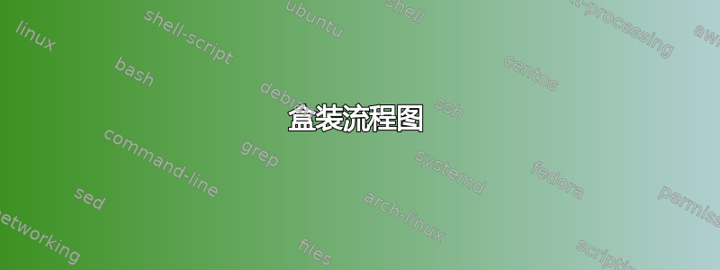
我想画一个像这样的 tikzpicture:

我尝试使用以下包:layers、matrix、fit+background,但是我对 tikz 还很陌生,无法使其工作,最初的想法是在背景中绘制框并将所有内容逐层放置在其上,但我了解到 tikz 不像这样工作:-/ 绘制一个没有额外框的简单流程图对我来说没有问题。
\pgfdeclarelayer{background layer}
\pgfsetlayers{background layer,main}
\begin{landscape}
\begin{figure}[!htb]
    \centering
    \begin{tikzpicture}[node distance = 0cm, auto,
    decision/.style = {diamond, draw, text width=6.5em, text badly centered, node distance=3cm, inner sep=0pt},
    block/.style = {rectangle, draw, text width=10em, text centered, rounded corners, minimum height=4em},
    block2/.style = {rectangle, draw, text width=5em, text centered, minimum height=4em},
    line/.style = {draw, -latex'},
    cloud/.style = {draw, ellipse, node distance=3cm,
    minimum height=2em}
    ]
    \begin{pgfonlayer}{background layer}
    \node [block2, minimum width=10cm, minimum height=10cm] (test) {};
    \end{pgfonlayer}{background layer}
    \begin{pgfonlayer}{background layer}
    \node [block2, above of=test, minimum width=10cm, minimum height=1cm, yshift=5.5cm] (test2) {test};
    \end{pgfonlayer}{background layer}
    \begin{pgfonlayer}{background layer}
    \node [block2, right of=test, xshift=10cm, minimum width=10cm, minimum height=10cm] (test3) {};
    \end{pgfonlayer}{background layer}
    \begin{pgfonlayer}{background layer}
    \node [block2, , above of=test3, minimum width=10cm, minimum height=1cm, yshift=5.5cm] (test4) {test};
    \end{pgfonlayer}{background layer}
    % Place nodes
    \node [block] (guss) {Gießprozess\\ (Stahlguss oder Sphäroguss)};
    \node [block2, right of=guss, node distance=5cm, minimum width=4cm, minimum height=6cm] (rahmen) {};
    \node [block, right of=rahmen, node distance=5cm] (vermessung) {Bauteilvermessung};
    \node [block, right of=vermessung, node distance=5cm] (bearbeitung) {Endbearbeitung};
    % Draw edges
    \path [line] (guss) -- (rahmen);
    \path [line] (rahmen) -- (vermessung);
    \path [line] (vermessung) -- (bearbeitung);
    \end{tikzpicture}
\end{figure}
\end{landscape}
答案1
起点:

\documentclass{article}
\usepackage[margin=25mm]{geometry}
\usepackage{pdflscape}
\usepackage{tikz}
\usetikzlibrary{arrows,
                calc,
                fit,
                positioning,
                shapes.geometric}


%\pgfdeclarelayer{background layer}
%\pgfsetlayers{background layer,main}
\begin{document}

\begin{landscape}
\begin{figure}[!htb]
    \centering
    \begin{tikzpicture}[
  node distance = 4mm and 8mm,
shorten <>/.style = {shorten >=#1, shorten <=#1},
     block/.style = {rectangle, draw, rounded corners,
                     fill=#1!30,
                     text width=6em, minimum height=4em, align=center},
%    block2/.style = {rectangle, draw, text width=5em, text centered, minimum height=4em},
      decision/.style = {diamond, aspect=1.3, draw,
                     text width=6.5em, align=flush center, inner sep=0pt},
       FIT/.style = {draw, inner xsep=4mm, inner ysep=#1},
      line/.style = {draw, -latex'},
     cloud/.style = {draw, ellipse, minimum height=2em}
                        ]
% Place nodes
\node (n1) [block=teal,text width=7em] {Gießprozess\\ (Stahlguss oder Sphäroguss)};
\node (n2) [block=red, right=of n1]         {2};
\node (n3a) [block=blue, above right=of n2] {3a};
\node (n3b) [block=blue, below right=of n2] {3b};
\node (n4) [block=blue, above right=of n3b] {4};
\node (n5) [block=teal, right=of n4]       {Bauteil\-vermessung};
\node (n6) [decision, right=of n5]          {6};
\node (n7) [block=gray, above=of n6]        {7};
\node (n8) [block=green,right=of n6]       {Endbear\-beitung};
\node (n9) [block=red, below=of n6]         {9};
% inner frame
\node (n10) [FIT=4mm,
             label=below:some text,
             fit=(n2) (n3a) (n3b) (n4)] {};
% outer frames
\node (n11) [FIT=6mm,
             fit=(n1) (n10) (n5)] {};
\path   let \p1 = ($(n11.west)-(n11.east)$),
            \n1 = {veclen(\x1,\y1)} in
        node[draw,
             fill=blue!40,
             minimum height=2em, inner sep=0pt,
             minimum width=\n1,
             above right=0pt of n11.north west] {some text};
\node (n12) [FIT=6mm,
             fit=(n6) (n10.north -| n7) (n10.south -| n9) (n8)] {};
\path   let \p1 = ($(n12.west)-(n12.east)$),
            \n1 = {veclen(\x1,\y1)} in
        node[draw,
             fill=blue!40,
             minimum height=2em, inner sep=0pt,
             minimum width=\n1,
             above right=0pt of n12.north west] {some text};
% Draw edges
\path[line] (n1)  edge (n10)
            (n2)  edge[bend left,shorten <>=2mm] (n3a)
            (n3a) edge[bend left,shorten <>=2mm] (n4)
            (n4)  edge[bend left,shorten <>=2mm] (n3b)
            (n3b) edge[bend left,shorten <>=2mm] (n2)
            (n10) edge (n5)
            (n7) edge (n6)
            (n6) edge (n8)
            (n6)  to  (n9);
\path[line] (n5) -- ($(n5.east)!0.75!(n6.west)$) |- (n7);
    \end{tikzpicture}
\end{figure}
\end{landscape}
目前尚不清楚,您是否还需要上图下方的节点。关于它,您没有在 mwe 中定义形状。