

考虑以下 MWE:
\documentclass[tikz]{standalone}
\usetikzlibrary{calc,backgrounds}
\tikzset{
    kolben/.style={
        append after command={
            \pgfextra{
                \node[fill=white,draw,minimum width=1.5cm,minimum height=1.3cm] (a) at (\tikzlastnode) {};
                \draw ($(a.north west)!.4!(a.south west)$) -- ($(a.north east)!.4!(a.south east)$);
                \draw ($(a.north west)!.35!(a.south west)$) -- ($(a.north east)!.35!(a.south east)$);
                \draw ($(a.north west)!.3!(a.south west)$) -- ($(a.north east)!.3!(a.south east)$);
                \draw ([yshift=-.2cm]$(a.north west)!.5!(a.south east)$) circle(.07);


            }
        }
    }
}
\begin{document}
\foreach \n in {0,1,...,36}
{
    \begin{tikzpicture}
        \pgfmathsetmacro{\x}{10*\n}
        \pgfmathsetmacro{\d}{(100/36)*\n}
        \useasboundingbox (-2,-2) rectangle (2,6);
%       \draw (0,0) circle(1);
            \begin{pgfonlayer}{background}
                \draw[rotate=\x] (0,.5) arc(90:270:.5) -- cycle;
            \end{pgfonlayer}
            \path (\x:1) -- ([yshift=3cm]0,{sin(\x)}) node[above,kolben] {};
                    \draw[double distance=15mm] (0,1.48) -- (0,4.78);
                            \fill[red!\d] ([xshift=-7.45mm]0,4.78) rectangle ([xshift=-.1mm]a.north east);
                        \draw[double distance=1mm] (0,0) -- (\x:1);
                        \draw[shorten >= -.5cm,double distance=1mm] (\x:1) -- (a);
            \draw (\x:1) -- ([yshift=3cm]0,{sin(\x)}) node[above,kolben] {};
                \fill[black,radius=.1] (\x:1) circle;
            \draw[->,red,ultra thick] (1.5,2.5) -- ([xshift=.75cm]a.north east);
            \ifnum\n>9
            \pgfmathsetmacro{\aa}{.5*\d}
                \fill[blue!\aa] ([xshift=-7.45mm]0,4.78) rectangle ([xshift=-.1mm]a.north east);
                    \fill[white] (1.3,2.5) rectangle ([xshift=.95cm]a.north east);
                \draw[<-,red,ultra thick] ([xshift=.75cm]a.south east) -- (1.5,4.8);
            \fi
            \ifnum\n>27
            \pgfmathsetmacro{\aa}{.2*\d}
                \fill[gray!\aa] ([xshift=-7.45mm]0,4.78) rectangle ([xshift=-.1mm]a.north east);
                \fill[white] (1.3,1) rectangle ([yshift=2.1cm,xshift=.95cm]a.north east);
                \draw[->,red,ultra thick] (1.5,1.5) -- ([xshift=.75cm]a.north east);
            \fi
    \end{tikzpicture}
}
\end{document}
如何改进代码(特别是带箭头的部分)?

答案1
我可能会做这样的事情:
\documentclass[tikz]{standalone}
\usetikzlibrary{backgrounds}

\tikzset{
    relative to node/.style={
        shift={(#1.center)},
        x={(#1.east)},
        y={(#1.north)},
    },
    kolben/.pic={
        \node[fill=white,draw,minimum width=1.5cm,minimum height=1.3cm] (-a) at (0,0.2) {};
        \begin{scope}[relative to node=-a]
            \draw (-1,0.2) -- ++(2,0);
            \draw (-1,0.3) -- ++(2,0);
            \draw (-1,0.4) -- ++(2,0);
        \end{scope}
        \draw (0,0) circle(0.07) coordinate (-pivot);
    }
}
\begin{document}
\foreach \x [evaluate=\x as \case using {int(mod(\x/90,4))}, evaluate=\x as \d using {10/36*\x}] in {0,10,...,359}
{
    \begin{tikzpicture}
        \useasboundingbox (-2,-2) rectangle (2,6);

        \pic (kolben) at (0,{3+sin(\x)}) {kolben};
            \fill[black,radius=.1] (\x:1) circle;

        \begin{pgfonlayer}{background}
            \draw[double distance=15mm] (0,1.45) -- (0,4.85);
            \draw[rotate=\x] (0,.5) arc(90:270:.5) -- cycle;
            \draw[double distance=1mm] (0,0) -- (\x:1);
            \draw[double distance=1mm] (\x:1) -- (kolben-pivot);
        \end{pgfonlayer}

        \node[anchor=base] at (1.25,3) {$ x $};
        \ifnum\x=0
            \fill[red] (1,3) circle (1.5pt);
        \else
            \ifnum\x=180
                \fill[red] (1,3) circle (1.5pt);
            \else
                \draw[->,red,ultra thick] (1,3) -- +(0,{sin(\x)});
            \fi
        \fi

        \node[anchor=base] at (1.75,3) {$ \dot{x} $};
        \ifnum\x=90
            \fill[blue] (1.5,3) circle (1.5pt);
        \else
            \ifnum\x=270
                \fill[blue] (1.5,3) circle (1.5pt);
            \else
                \draw[->,blue,ultra thick] (1.5,3) -- +(0,{cos(\x)});
            \fi
        \fi

        \ifcase\case
            \draw[line width=14.9mm,red!\d] (kolben-a.north) -- (0,4.85);
        \or
            \pgfmathsetmacro{\aa}{.5*\d}
            \draw[line width=14.9mm,blue!\aa] (kolben-a.north) -- (0,4.85);
        \or
            \pgfmathsetmacro{\aa}{.5*\d}
            \draw[line width=14.9mm,blue!\aa] (kolben-a.north) -- (0,4.85);
        \or
            \pgfmathsetmacro{\aa}{.2*\d}
            \draw[line width=14.9mm,gray!\aa] (kolben-a.north) -- (0,4.85);
        \fi

    \end{tikzpicture}
}
\end{document}
我所做的更改:
- 我使用了
\x度数,这样您就可以根据需要获得流畅的动画,最多可达到一度的步长,只需改变 foreach 列表中的第二个条目即可; - 我将动画分为四种情况(象限),其中气体颜色发生了变化(我没有触及实际的颜色,因为无论如何我都不知道如何处理它们);
- 我不断地从一点,我认为如果箭头的起点改变的话会分散注意力;
- 我在箭头中添加了一个物理量,因为如果注释背后没有任何想法,你不妨省略它们;
- 我将
kolben样式改为pic,因为如果\pgfextra不需要,您可能不应该使用它。 - 其余的变化可能是个人编码偏好,并没有真正增加功能,但你总是可以通过看到不同的代码做同样的事情来学习:)
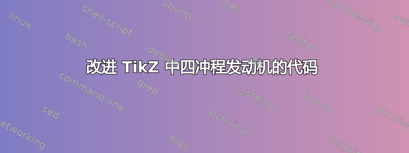
结果当然是:

编辑
只是为了好玩,一些小小的美学改进,并尝试显示引擎的状态,如所述斯基尔蒙:

代码:
\documentclass[tikz]{standalone}
\usetikzlibrary{shapes}

\tikzset{
    relative to node/.style={
        shift={(#1.center)},
        x={(#1.east)},
        y={(#1.north)},
    },
    kolben/.pic={
        \node[fill=white,draw,minimum width=1.5cm,minimum height=1.3cm] (-a) at (0,0.2) {};
        \begin{scope}[relative to node=-a]
            \draw (-1,0.2) -- ++(2,0);
            \draw (-1,0.3) -- ++(2,0);
            \draw (-1,0.4) -- ++(2,0);
        \end{scope}
        \draw (0,0) circle(0.07);
    },
    valve/.pic={
        \draw[fill=white] (-0.175,0) -- (-0.125,0.05) -- (-0.05,0.05) -- (-0.05,0.15) -- (-0.075,0.15) -- (-0.075,0.2) -- (0.075,0.2) -- (0.075,0.15) -- (0.05,0.15) -- (0.05,0.05) -- (0.125,0.05) -- (0.175,0) -- cycle;
    },
    cylinder/.pic={
        \draw (-0.75,1.55) -- (-0.8,1.55) -- (-0.8,5.05) -- (-0.5,5.05) -- (-0.55,5) -- (-0.75,5) -- cycle;
        \draw (-0.25,5.05) -- (-0.2,5) -- (0.2,5) -- (0.25,5.05) -- cycle;
        \draw[xscale=-1] (-0.75,1.55) -- (-0.8,1.55) -- (-0.8,5.05) -- (-0.5,5.05) -- (-0.55,5) -- (-0.75,5) -- cycle;
    },
    crank/.pic={
        \draw[fill=white,rounded corners=1mm] (90:0.75) arc (90:270:0.75) -- (0,-0.1) [rounded corners=0mm] -- (1,-0.1) arc (-90:90:0.1) [rounded corners=1mm] -- (0,0.1) -- cycle (1,0) circle (0.05);
    }
}

\begin{document}
\foreach \phase [
    evaluate=\phase as \x using {int(mod(\phase + 90,360))},
    evaluate=\phase as \case using {int(mod(\phase/180,4))},
    evaluate=\x as \d using {40*sin(\x)+50},
] in {0,5,...,719}{
    \begin{tikzpicture}
        \useasboundingbox (-2,-2) rectangle (2,6);

        \coordinate (pivot) at (0,{3+sin(\x)});
        \coordinate (piston-top) at (0,{3+sin(\x)+1.3/2+0.2});

        \ifcase\case
            \colorlet{gascolor}{blue!10}
            \pgfmathsetmacro\valveone{1}
            \pgfmathsetmacro\valvetwo{0}
        \or
            \colorlet{gascolor}{blue!\d}
            \pgfmathsetmacro\valveone{0}
            \pgfmathsetmacro\valvetwo{0}
        \or
            \colorlet{gascolor}{red!\d}
            \pgfmathsetmacro\valveone{0}
            \pgfmathsetmacro\valvetwo{0}
        \or
            \colorlet{gascolor}{gray!10}
            \pgfmathsetmacro\valveone{0}
            \pgfmathsetmacro\valvetwo{1}
        \fi

        \draw[line width=14.9mm,gascolor] (piston-top) -- (0,5);

        \pic (cylinder) at (0,0) {cylinder};

        \pic (valve1) at (-0.375,{5-0.1*\valveone}) {valve};
        \pic (valve2) at (0.375,{5-0.1*\valvetwo}) {valve};


        \draw[double distance=2mm-\pgflinewidth,line cap=round] (\x:1) -- (pivot);

        \pic[rotate=\x] (crank) at (0,0) {crank};
        \pic (kolben) at (pivot) {kolben};

        \node[anchor=base] at (1.25,3) {$ x $};
        \ifnum\x=0
            \fill[red] (1,3) circle (1.5pt);
        \else
            \ifnum\x=180
                \fill[red] (1,3) circle (1.5pt);
            \else
                \draw[->,red,ultra thick] (1,3) -- +(0,{sin(\x)});
            \fi
        \fi

        \node[anchor=base] at (1.75,3) {$ \dot{x} $};
        \ifnum\x=90
            \fill[blue] (1.5,3) circle (1.5pt);
        \else
            \ifnum\x=270
                \fill[blue] (1.5,3) circle (1.5pt);
            \else
                \draw[->,blue,ultra thick] (1.5,3) -- +(0,{cos(\x)});
            \fi
        \fi

        \ifnum\phase=360
            \begin{scope}
                \clip (-7.5mm,5cm-0.5\pgflinewidth) rectangle (7.5mm,3cm);
                \node[starburst,starburst point height=3mm,inner color=yellow,outer color=red,draw=orange] at (0,5) {};
            \end{scope}
        \fi

    \end{tikzpicture}
}
\end{document}