

以下是我的 MWE。我了解 tikz 和 foreachs 的要点,但谈到变量时,我还不太明白。
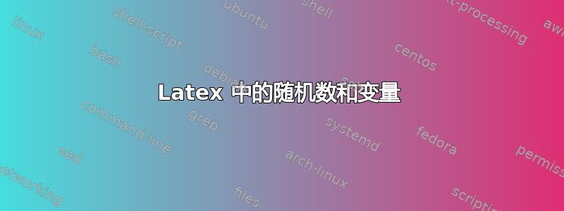
我想要一个从每个单元指向一个模块的箭头,然后从模块指向集群输出。
如你所见,我得到了循环,但我不知道如何获取随机数。我得到了兰特可以工作,但是会产生下面所示的输出。
我想到两种方法:
创建一个 if 语句来检查 rand 数是多少,并将其链接到模块。例如 rand == 1 -> Module 1; rand == 2 Module 2; rand == 3 Module 875 等等。我无法让它像这样工作
\ifnum\rand=1从一组中获取一个随机数。
我更喜欢方法 2,但如果您能给我提供任何有关如何操作的提示,我将非常高兴!
任何帮助都值得感激!
\documentclass[
a4paper,            %   Papierformat A4
12pt,               %   Schrift 12-Punkt
headsepline,        %   mit Linie unter der Kopfzeile
numbers=noenddot,   %   Nummern ohne Punkt am Ende
bibliography=totoc, %   Literaturverzeichnis mit Nummer im
Inhaltsverzeichnis (``TO Table Of Contents'')
index=totoc,        %   Index mit Nummer im Inhaltsverzeichnis
fleqn,              %   Formeln werden linksbündig statt zentriert
angeordnet
headings=normal     %       Etwas kleinere Überschriften
]{scrreprt}
\usepackage{tikz}
\usepackage{subfigure}
\usepackage{adjustbox}
\usepackage{graphics}
\usepackage[first=1, last=4]{lcg}
\usetikzlibrary{matrix, positioning}


\begin{document}

    \begin{figure}[!htb]

    \begin{tikzpicture}[font=\sffamily]
    \matrix[matrix of nodes, nodes in empty cells, column sep=-\pgflinewidth, row sep=-\pgflinewidth,
    nodes = {minimum height=7mm, minimum width=1cm, anchor=center, draw, fill=white, inner sep=0, outer sep = 0},
    %column 1/.style={nodes={fill=orange}},
    %row 1/.style={nodes={fill=green}},
    %row 1 column 1/.style={nodes={draw=none, fill=none}},
    w/.style={fill=white},
    label=above:Digi Input] (Clusters) {
        &&&&&&&&&&&&&&&\\[10cm]
    };

    \node[draw, shape=rectangle, minimum height=4cm,minimum width=3cm] at (-6.5,-4) {Modul 1};
    \node[draw, shape=rectangle, minimum height=4cm,minimum width=3cm] at (-2.5,-4) {Modul 2};
    \node[ minimum height=4cm,minimum width=3cm] at (0,-4) {$\cdots$};
    \node[draw, shape=rectangle, minimum height=4cm,minimum width=3cm] at (2.5,-4) {Modul 875};
    \node[draw, shape=rectangle, minimum height=4cm,minimum width=3cm] at (6.5,-4) {Modul 876};
    \pgfmathdeclarerandomlist{modules}{{-6.5}{-2.5}{2.5}{6.5}}
    %\foreach \x in {1,2,...,5}
    \newcounter{myrandom}{rand}
    \foreach \x in {-7.5, -6.5,..., 7.5}
        {   %\rand;
            \pgfmathrandomitem{\num}{modules}
            \draw [->, line width=0.5mm] (\x,-0.35) -- (\num,-2);}
    %\draw [fill=gray] (-8,-4) rectangle (-6,-1);
    %\draw [->, line width=0.5mm] (-7.5,-0.35) -- (-7,-0.95);
    %\node[font=\Huge\sffamily, draw] {Skippd};
    %\node[font=\Huge\sffamily, below left=0pt of Clusters-3-14.north east] {Skipped};


    \matrix[matrix of nodes, nodes in empty cells, column sep=-\pgflinewidth, row sep=-\pgflinewidth,
    nodes = {minimum height=7mm, minimum width=1cm, anchor=center, draw, fill=white},
    %column 1/.style={nodes={fill=orange}},
    %row 1/.style={nodes={fill=green}},
    %row 1 column 1/.style={nodes={draw=none, fill=none}},
    w/.style={fill=white},
    label=below:Cluster Output] at (0,-8)(Cluster Output) {
        &&&&&&&&&&&&&&&\\
    };
    \end{tikzpicture}
    \begin{tikzpicture}[font=\sffamily]
    \matrix[matrix of nodes, nodes in empty cells, column sep=-\pgflinewidth, row sep=-\pgflinewidth,
    nodes = {minimum height=7mm, minimum width=1cm, anchor=center, draw, fill=white, inner sep=0, outer sep = 0},
    %column 1/.style={nodes={fill=orange}},
    %row 1/.style={nodes={fill=green}},
    %row 1 column 1/.style={nodes={draw=none, fill=none}},
    w/.style={fill=white},
    label=above:Digi Input] (Clusters) {
        &&&&&&&&&&&&&&&\\[10cm]
    };

    \node[draw, shape=rectangle, minimum height=4cm,minimum width=3cm] at (-6.5,-4) {Modul 1};
    \node[draw, shape=rectangle, minimum height=4cm,minimum width=3cm] at (-2.5,-4) {Modul 2};
    \node[ minimum height=4cm,minimum width=3cm] at (0,-4) {$\cdots$};
    \node[draw, shape=rectangle, minimum height=4cm,minimum width=3cm] at (2.5,-4) {Modul 875};
    \node[draw, shape=rectangle, minimum height=4cm,minimum width=3cm] at (6.5,-4) {Modul 876};

    %\draw [->, line width=0.5mm] (-7.5,-0.35) -- (-6.5,-2);
    %\draw [fill=gray] (-8,-4) rectangle (-6,-1);
    %\draw [->, line width=0.5mm] (-7.5,-0.35) -- (-7,-0.95);
    %\node[font=\Huge\sffamily, draw] {Skippd};
    %\node[font=\Huge\sffamily, below left=0pt of Clusters-3-14.north east] {Skipped};


    \matrix[matrix of nodes, nodes in empty cells, column sep=-\pgflinewidth, row sep=-\pgflinewidth,
    nodes = {minimum height=7mm, minimum width=1cm, anchor=center, draw, fill=white},
    %column 1/.style={nodes={fill=orange}},
    %row 1/.style={nodes={fill=green}},
    %row 1 column 1/.style={nodes={draw=none, fill=none}},
    w/.style={fill=white},
    label=below:Cluster Output] at (0,-8)(Cluster Output) {
        &&&&&&&&&&&&&&&\\
    };
    \end{tikzpicture}
    \caption{Lokale Rekonstruktion}
    \end{figure}
\end{document}
答案1
pgf 附带一个工具,可以从列表中随机选择一个项目。在您的示例中,可以像您所说的那样
\pgfmathdeclarerandomlist{modules}{{1}{2}{3}{4}}
\pgfmathrandomitem{\num}{modules}
这是我们在评论中对话的总结。至于你的问题:“你是否有快速的想法,如何防止箭头重叠太多?”:不,我没有神奇的工具可以解开箭头。我能提供的是让箭头颜色取决于模块和传入箭头的角度,这可以说是更好一些。
\documentclass[
a4paper,            %   Papierformat A4
12pt,               %   Schrift 12-Punkt
headsepline,        %   mit Linie unter der Kopfzeile
numbers=noenddot,   %   Nummern ohne Punkt am Ende
bibliography=totoc, %   Literaturverzeichnis mit Nummer im
Inhaltsverzeichnis (``TO Table Of Contents'')
index=totoc,        %   Index mit Nummer im Inhaltsverzeichnis
fleqn,              %   Formeln werden linksbündig statt zentriert
angeordnet
headings=normal     %       Etwas kleinere Überschriften
]{scrreprt}
\usepackage{tikz}
\usetikzlibrary{matrix, positioning,calc}

\begin{document}
\begin{figure}[!htb]
\begin{tikzpicture}[font=\sffamily]
    \matrix[matrix of nodes, nodes in empty cells, column sep=-\pgflinewidth, row sep=-\pgflinewidth,
    nodes = {minimum height=7mm, minimum width=1cm, anchor=center, draw, fill=white, inner sep=0, outer sep = 0},
    %column 1/.style={nodes={fill=orange}},
    %row 1/.style={nodes={fill=green}},
    %row 1 column 1/.style={nodes={draw=none, fill=none}},
    w/.style={fill=white},
    label=above:Digi Input] (Clusters) {
        &&&&&&&&&&&&&&&\\[10cm]
    };

    \node[draw, shape=rectangle, minimum height=4cm,minimum width=3cm]
     (module-1) at (-6.5,-4) {Modul 1};
    \node[draw, shape=rectangle, minimum height=4cm,minimum width=3cm]
     (module-2) at (-2.5,-4) {Modul 2};
    \node[ minimum height=4cm,minimum width=3cm] at (0,-4) {$\cdots$};
    \node[draw, shape=rectangle, minimum height=4cm,minimum width=3cm]
     (module-3) at (2.5,-4) {Modul 875};
    \node[draw, shape=rectangle, minimum height=4cm,minimum width=3cm]
     (module-4)at (6.5,-4) {Modul 876};


    \matrix[matrix of nodes, nodes in empty cells, column sep=-\pgflinewidth, row sep=-\pgflinewidth,
    nodes = {minimum height=7mm, minimum width=1cm, anchor=center, draw, fill=white},
    %column 1/.style={nodes={fill=orange}},
    %row 1/.style={nodes={fill=green}},
    %row 1 column 1/.style={nodes={draw=none, fill=none}},
    w/.style={fill=white},
    label=below:Cluster Output] at (0,-8)(Cluster Output) {
        &&&&&&&&&&&&&&&\\
    };

    \pgfmathdeclarerandomlist{modules}{{1}{2}{3}{4}}
    \edef\LstColors{"black","red","green!70!black","blue"}
    \foreach \Y in {1,...,16}
        {   %\rand;
            \pgfmathrandomitem{\num}{modules}
            \pgfmathsetmacro{\mycolor}{{\LstColors}[\num-1]}
            \path (Clusters-1-\Y.south) --  (module-\num.90-2*\Y+17)
            coordinate[pos=0.4] (aux0) coordinate[pos=0.5] (aux1);
            \draw [-latex,thick,\mycolor] let \p1=($(aux1)-(aux0)$),
            \n1={atan2(\y1,\x1)} in
            (Clusters-1-\Y.south) to[out=-90,in=\n1+180]
            (aux0) -- (aux1) to[out=\n1,in=90]  (module-\num.90-4*\Y+34);}
%
%   \foreach \X in {1,2,875,876}
%   {\foreach \Y in {1,...,16}
%   {\draw[-latex,thick] (Clusters-1-\Y.south) to (module-\X.north);
%   \draw[-latex,thick] (module-\X.south) to (Cluster Output-1-\Y.north);}}

    \end{tikzpicture}
    \caption{Lokale Rekonstruktion}
    \end{figure}
\end{document}

如果你用以下方式替换循环
\pgfmathdeclarerandomlist{modules}{{1}{2}{3}{4}}
\edef\LstColors{"black","red","green!70!black","blue"}
\foreach \Y in {1,...,16}
    {   %\rand;
        \pgfmathrandomitem{\num}{modules}
        \pgfmathsetmacro{\mycolor}{{\LstColors}[\num-1]}
        \draw[thick,-latex,\mycolor] (Clusters-1-\Y.south)
        to[out=-90,in=90,looseness=0.3]  (module-\num.90-4*\Y+34);}
你得到
