

我有一些自动放置的节点,应该用图案填充。但是,我注意到图案偏移取决于节点位置,这会使节点看起来不同。
最小示例:
\documentclass[tikz,border=5mm]{standalone}
\usetikzlibrary{patterns}

\begin{document}
\begin{tikzpicture}
\foreach \n in {0,1,...,5}
{
    \node [rectangle,draw,minimum width=1cm,minimum height=1cm,pattern=north west lines] at (1.1*\n cm, 0) {};
    \node [rectangle,draw,minimum width=1cm,minimum height=1cm,pattern=dots] at (1.1*\n cm, 1.1) {};
}
\end{tikzpicture}
\end{document}

如何才能实现每个节点的图案都相同?我认为我必须为此调整一些图案原点。
答案1
该patterns.meta库具有允许人们移动模式的键。这适用于模式Dots。对于Lines模式,库中的转换顺序在我看来不方便。所以我添加了一个版本MovableLines,可以以一种更直观的方式移动它。1
\documentclass[tikz,border=5mm]{standalone}
\usetikzlibrary{patterns.meta}

\pgfdeclarepattern{
  name=MovableLines,
  parameters={
      \pgfkeysvalueof{/pgf/pattern keys/distance},
      \pgfkeysvalueof{/pgf/pattern keys/angle},
      \pgfkeysvalueof{/pgf/pattern keys/xshift},
      \pgfkeysvalueof{/pgf/pattern keys/yshift},
      \pgfkeysvalueof{/pgf/pattern keys/line width},
  },
  bottom left={%
    \pgfpoint
      {-.5*(\pgfkeysvalueof{/pgf/pattern keys/distance})}%
      {-.5*(\pgfkeysvalueof{/pgf/pattern keys/distance})}},
  top right={%
    \pgfpoint
      {.5*(\pgfkeysvalueof{/pgf/pattern keys/distance})}%
      {.5*(\pgfkeysvalueof{/pgf/pattern keys/distance})}},
  tile size={%
    \pgfpoint
      {\pgfkeysvalueof{/pgf/pattern keys/distance}}%
      {\pgfkeysvalueof{/pgf/pattern keys/distance}}},
  tile transformation={%
    \pgftransformshift{%
      \pgfpoint
        {\pgfkeysvalueof{/pgf/pattern keys/xshift}}%
        {\pgfkeysvalueof{/pgf/pattern keys/yshift}}}%
    \pgftransformrotate{\pgfkeysvalueof{/pgf/pattern keys/angle}}},
  defaults={
    distance/.initial=3pt,
    angle/.initial=0,
    xshift/.initial=0pt,
    yshift/.initial=0pt,
    line width/.initial=\the\pgflinewidth,
  },
  code={%
    \pgfsetlinewidth{\pgfkeysvalueof{/pgf/pattern keys/line width}}%
    \pgfpathmoveto{\pgfpoint{-.5*(\pgfkeysvalueof{/pgf/pattern keys/distance})}{0pt}}%
    \pgfpathlineto{\pgfpoint{.5*(\pgfkeysvalueof{/pgf/pattern keys/distance})}{0pt}}%
    \pgfusepath{stroke}%
  },
}


\begin{document}
\begin{tikzpicture}
\foreach \n in {0,1,...,5}
{
    \node [rectangle,draw,minimum width=1cm,minimum height=1cm,
    pattern={MovableLines[angle=-45,distance={sqrt(0.5)*3pt},
       line width=0.4pt]}] at (1.1*\n cm, 0) {};
    \node [rectangle,draw,minimum width=1cm,minimum height=1cm,
     pattern=Dots] at (1.1*\n cm, 1.1) {};
}
\end{tikzpicture}

\begin{tikzpicture}
\foreach \n in {0,1,...,5}
{
    \node [rectangle,draw,minimum width=1cm,minimum height=1cm,
    pattern={MovableLines[xshift={1.1*\n cm},angle=-45,distance={sqrt(0.5)*3pt},
       line width=0.4pt]}] at (1.1*\n cm, 0) {};
     \node [rectangle,draw,minimum width=1cm,minimum height=1cm,
     pattern={Dots[xshift={1.1*\n cm}]}] at (1.1*\n cm, 1.1) {};
}
\end{tikzpicture}

\end{document}

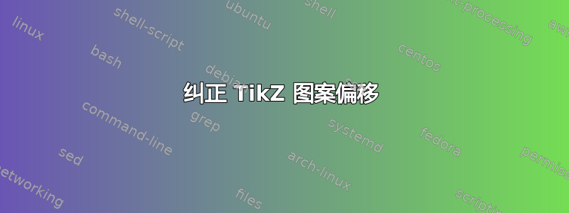
在上图中,没有应用任何移位,矩形看起来不同。在下面图中,我们根据节点的水平位置进行移位,矩形看起来相同。
人们还可以将模式转换作为节点定义的一部分,但这需要一些额外的工作。
最后,让我说一下,模式是棘手的(好吧,我们知道这一点;-):如果你将生成的 pdf 转换为另一种格式,模式可能会发生改变。
1当然,你也可以改变原来的线条,只需逆向设计这种转变即可。参见这里对于转换和功能请求,可以以更直观的方式更改顺序或添加可以移动的版本。