

尝试绘制两个耦合摆的机械系统,我使用了以下代码:
\documentclass[11pt]{article}

\usepackage{tikz,pgfplots}

\usetikzlibrary{intersections,calc,patterns,angles,quotes,}

\pgfplotsset{compat=1.11}
\usetikzlibrary{arrows.meta}
\usetikzlibrary{
   decorations.markings,
   decorations.pathmorphing,
   decorations.pathreplacing,
   calc,
   patterns,
   positioning
}
\tikzset{
      spring/.style={thick,decorate,decoration={zigzag,pre length=0.3cm,post length=0.3cm,segment length=6}},
      blank/.style={draw=none,fill=none,pos=0.5},
      ground/.style={fill,pattern=north east lines,draw=none,minimum width=0.5cm,minimum height=0.3cm},
      damper/.style={thick,
         decoration={markings, mark connection node=dmp,
           mark=at position 0.5 with
          {
            \node (dmp) [thick,inner sep=0pt,transform shape,rotate=-90,minimum width=10pt,minimum height=3pt,draw=none] {};
            \draw [thick] ($(dmp.north east)+(2pt,0)$) -- (dmp.south east) -- (dmp.south west) -- ($(dmp.north west)+(2pt,0)$);
            \draw [thick] ($(dmp.north)+(0,-3pt)$) -- ($(dmp.north)+(0,3pt)$);
          }
          }, decorate
      },
     box/.style={draw,thick,minimum width=1cm, minimum height=1cm}
    }


\begin{document}

\begin{figure}[htbp]
\centering
\begin{tikzpicture}[dot/.style={circle,inner sep=1pt,fill,label={#1},name=#1},
  extended line/.style={shorten >=-#1,shorten <=-#1},
  extended line/.default=0cm]

\node (wall) [ground, minimum width=4cm] {};
\draw (wall.south east) -- (wall.south west);

\pgfmathsetmacro{\myAngle}{30}

    \coordinate (pivot1) at (-1,-0.16);
    \draw[thick,-] (pivot1) -- ++ (0,-4)
    node (bob1) [draw,fill=gray!40,circle,minimum size=6pt,inner sep=6pt]{$$}
    node (resort1) [midway,left]{$$};

    \coordinate (pivot2) at (1,-0.16);
    \draw[thick,-] (pivot2) -- ++ (0,-4)
    node (bob2) [draw,fill=gray!40,circle,minimum size=6pt,inner sep=6pt]{$$}
    node (resort2) [midway,right]{$$};

    \draw[spring] (resort1) -- (resort2) node[blank,above,yshift=0mm] {$ $};

    \draw[decorate,decoration={brace,amplitude=.3cm}] (pivot2.west) -- (resort2.west) node[blank,right] {$l$};
     \draw[decorate,decoration={brace,mirror,amplitude=.7cm}] (pivot1.east) to ($(bob1)+(0.02,0.475)$) node[blank,left,xshift=-1.65cm,yshift=-1.9cm] {$L$};

\end{tikzpicture}
\end{figure}

\begin{figure}[htbp]
\centering
\begin{tikzpicture}[dot/.style={circle,inner sep=1pt,fill,label={#1},name=#1},
  extended line/.style={shorten >=-#1,shorten <=-#1},
  extended line/.default=0cm]

\node (wall) [ground, minimum width=4cm] {};
\draw (wall.south east) -- (wall.south west);

\pgfmathsetmacro{\myAngle}{30}

    \coordinate (pivot1) at (-1,-0.16);
    \draw[thick,densely dotted,-] (pivot1) -- ++ (0,-1) node (vertical1) [black,below]{$ $};
    \draw[thick] (pivot1) -- ++ (270+\myAngle:4cm)
    node (bob1) [draw,fill=gray!40,circle,minimum size=6pt,inner sep=6pt]{$ $}
    node (spring1) [midway,left]{$$};
    \pic [draw, -,"$\theta_1$", angle eccentricity=1.5] {angle = vertical1--pivot1--bob1};

    \coordinate (pivot2) at (1,-0.16);
    \draw[thick,densely dotted,-] (pivot2) -- ++ (0,-1) node (vertical2) [black,below]{$ $};
    \draw[thick] (pivot2) -- ++(270+\myAngle:4cm)
    node (bob2) [draw,fill=gray!40,circle,minimum size=6pt,inner sep=6pt]{$ $}
    node (spring2) [midway,right]{$$};
    \pic [draw, -,font=\small, "$\theta_2$", angle eccentricity=1.5] {angle = vertical2--pivot2--bob2};

    \draw[spring] (spring1) -- (spring2) node[blank,above,xshift=-4mm,yshift=0mm] {$ $};

    \draw [thick,densely dotted,extended line, name path=A] (spring1) -- (spring2);
    \draw [thick,densely dotted,extended line,name path=E] ($(spring1)!1cm!(spring2)$) -- ($(spring1)!-.88cm!(spring2)$);

    \draw [thick,densely dotted,extended line, name path=B] ($(spring1)!(pivot1)!(spring2)$) -- (pivot1);

    \draw [thick,densely dotted,extended line, name path=C] ($(spring1)!(pivot2)!(spring2)$) -- (pivot2);

    \draw[decorate,decoration={brace,amplitude=.3cm}] (pivot1.east) -- (spring1.east) node[blank,right] {$l$};

    \node[name intersections={of= E and B}] (P1) at (intersection-1) {$ $};
    \node[name intersections={of= A and C}] (P2) at (intersection-1) {$ $};

    \draw[decorate,decoration={brace,mirror,amplitude=.25cm}] ($(P1)-(0,0)$) to ($(spring1)+(0.15,0)$) node[blank,below,xshift=-0.5cm,yshift=-2.1cm] {$x$};

    \draw[decorate,decoration={brace,amplitude=.25cm}] (spring2) to ($(P2)+(0,0)$) node[blank,below,xshift=1.5cm,yshift=-2.1cm] {$y$};
    \draw[decorate,decoration={brace,amplitude=.7cm}] (pivot2.east) to ($(bob2)+(-0.25,0.4)$) node[blank,left,xshift=2.95cm,yshift=-1.3cm] {$L$};
\end{tikzpicture}
\end{figure}

\end{document}
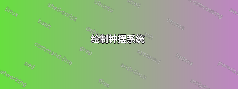
输出为:

这些数字存在一些问题。
- 第二个图形不像第一个图形那样居中。
- 弦长上的支架
L没有正确地将枢轴和摆锤连接起来。 l连接枢轴和弹簧连接点的段长度上的支架标题位置不正确。x我想知道是否有办法自动设置用和表示的括号的末端y。
我该如何修复它们?
答案1
第二幅图是居中,两个图中的“墙”不对齐,因为第二个图比第一个图宽。要使它们对齐,例如,您可以将两个图放在相同的
tikzpicture,使用 ascope将第二个向下移动:\begin{tikzpicture} <code for first diagram> \begin{scope}[yshift=-6cm] <code for second diagram> \end{scope} \end{tikzpicture}在这种情况下,您当然必须删除第一个
\end{tikzpicture}\end{figure}和第二个。\begin{figure}\centering\begin{tikzpicture}如果您想要保留单独的数字,并且不考虑最右边的摆锤进行定心,您可以添加
\useasboundingbox (wall.north west) rectangle ([yshift=-4cm]wall.east);紧接着
\node (wall) [ground, minimum width=4cm] {};第二张图。下面的代码演示了两者。
您已明确告诉 TikZ 停止括号内的圆珠笔画,例如
($(bob1)+(0.02,0.475)$)。使用 just(bob1),括号就会停止在应停止的位置。(如果我理解正确的话。)使用 时
to,任何沿路径放置的节点都必须放置在to和 下一个坐标之间。即你需要\draw (0,0) to node {foo} (2,2);并不是
\draw (0,0) to (2,2) node[midway] {foo};后一种情况不起作用,这就是为什么您需要所有这些
xshifts 和yshifts。但是,当使用
--而不是 时,to\draw (0,0) -- (2,2) node[midway] {foo};做工作,并且foo节点位于中间点。您可以使用垂直坐标 (TikZ:箭头的 |- 符号到底起什么作用?)定义括号左端点的坐标。例如,
\coordinate (c1) at (pivot1 |- spring1);c1然后从到画出括号spring1。我认为,通过定义坐标(例如,
c1您不需要vertical1坐标、交叉点或坐标计算),您使这个问题变得比需要的更复杂。
这是代码的修改版本。除了上面提到的一些内容之外,我还将spring和resort节点设为坐标(因此您不必担心锚点等。它们只是点),并且我将常用样式定义移至\tikzset序言中的,并为节点创建了新样式bob。哦,我还删除了一些空节点,如果它们没有使用,它们只会使代码变得混乱。

\documentclass[11pt]{article}

\usepackage{tikz}
\usetikzlibrary{
   angles,
   quotes,
   arrows.meta,
   decorations.markings,
   decorations.pathmorphing,
   decorations.pathreplacing,
   calc,
   patterns,
   positioning
}
\tikzset{
      spring/.style={thick,decorate,decoration={zigzag,pre length=0.3cm,post length=0.3cm,segment length=6}},
      blank/.style={draw=none,fill=none,pos=0.5},
      ground/.style={fill,pattern=north east lines,draw=none,minimum width=0.5cm,minimum height=0.3cm},
      damper/.style={thick,
         decoration={markings, mark connection node=dmp,
           mark=at position 0.5 with
          {
            \node (dmp) [thick,inner sep=0pt,transform shape,rotate=-90,minimum width=10pt,minimum height=3pt,draw=none] {};
            \draw [thick] ($(dmp.north east)+(2pt,0)$) -- (dmp.south east) -- (dmp.south west) -- ($(dmp.north west)+(2pt,0)$);
            \draw [thick] ($(dmp.north)+(0,-3pt)$) -- ($(dmp.north)+(0,3pt)$);
          }
          }, decorate
      },
     box/.style={draw,thick,minimum width=1cm, minimum height=1cm},
     dot/.style={circle,inner sep=1pt,fill,label={#1},name=#1},
     extended line/.style={shorten >=-#1,shorten <=-#1},
     extended line/.default=0cm,
     bob/.style={draw,fill=gray!40,circle,minimum size=6pt,inner sep=6pt}
    }


\begin{document}

\begin{figure}[htbp]
\centering
\begin{tikzpicture}

\node (wall) [ground, minimum width=4cm] {};
\draw (wall.south east) -- (wall.south west);


    \coordinate (pivot1) at (-1,-0.16);
    \draw[thick,-] (pivot1) -- ++ (0,-4)
      node (bob1) [bob]{}
      coordinate [midway] (resort1);

    \coordinate (pivot2) at (1,-0.16);
    \draw[thick,-] (pivot2) -- ++ (0,-4)
      node (bob2) [bob]{}
      coordinate [midway] (resort2);

    \draw[spring] (resort1) -- (resort2);

    \draw[decorate,decoration={brace,amplitude=.35cm}] (pivot2) -- node[right=3mm] {$l$} (resort2);
     \draw[decorate,decoration={brace,mirror,amplitude=.35cm}] (pivot1) to node[left=3mm] {$L$} (bob1);

\end{tikzpicture}
\end{figure}

\begin{figure}[htbp]
\centering
\begin{tikzpicture}
\node (wall) [ground, minimum width=4cm] {};

\useasboundingbox (wall.north west) rectangle ([yshift=-4cm]wall.east);

\draw (wall.south east) -- (wall.south west);

\pgfmathsetmacro{\myAngle}{30}

    \coordinate (pivot1) at (-1,-0.16);
    \draw[thick] (pivot1) -- ++ (270+\myAngle:4cm)
      node (bob1) [bob]{}
      coordinate [midway] (spring1);

    \coordinate (c1) at (pivot1|-spring1);

    \pic [draw, -,"$\theta_1$", angle eccentricity=1.5] {angle = c1--pivot1--bob1};

    \coordinate (pivot2) at (1,-0.16);
    \draw[thick] (pivot2) -- ++(270+\myAngle:4cm)
      node (bob2) [bob]{}
      coordinate [midway] (spring2);
    \coordinate (c2) at (pivot2|-spring2);

    \pic [draw, font=\small, "$\theta_2$", angle eccentricity=1.5] {angle = c2--pivot2--bob2};

    \draw[spring] (spring1) -- (spring2);

    \draw [thick, densely dotted] (pivot1) |- (spring1);
    \draw [thick, densely dotted] (pivot2) |- (spring2);

    \draw[decorate,decoration={brace,mirror,amplitude=.25cm}] (c1) -- node[below=2mm] {$x$} (spring1);
    \draw[decorate,decoration={brace,mirror,amplitude=.25cm}] (c2) -- node[below=2mm] {$y$} (spring2);

    \draw[decorate,decoration={brace,amplitude=.35cm}] (pivot1) --node[blank,right=3mm,yshift=2mm] {$l$} (spring1);

    \draw[decorate,decoration={brace,amplitude=.35cm}] (pivot2) -- node[blank,right=3mm,yshift=2mm] {$L$}(bob2) ;
\end{tikzpicture}
\end{figure}

%% both in the same tikzpicture/figure might be more appropriate

\begin{figure}[htbp]
\centering
\begin{tikzpicture}

\node (wall) [ground, minimum width=4cm] {};
\draw (wall.south east) -- (wall.south west);


    \coordinate (pivot1) at (-1,-0.16);
    \draw[thick,-] (pivot1) -- ++ (0,-4)
      node (bob1) [bob]{}
      coordinate [midway] (resort1);

    \coordinate (pivot2) at (1,-0.16);
    \draw[thick,-] (pivot2) -- ++ (0,-4)
      node (bob2) [bob]{}
      coordinate [midway] (resort2);

    \draw[spring] (resort1) -- (resort2);

    \draw[decorate,decoration={brace,amplitude=.35cm}] (pivot2) -- node[right=3mm] {$l$} (resort2);
     \draw[decorate,decoration={brace,mirror,amplitude=.35cm}] (pivot1) to node[left=3mm] {$L$} (bob1);

\begin{scope}[yshift=-5.3cm]
\node (wall) [ground, minimum width=4cm] {};

\useasboundingbox (wall.north west) rectangle ([yshift=-4cm]wall.east);

\draw (wall.south east) -- (wall.south west);

\pgfmathsetmacro{\myAngle}{30}

    \coordinate (pivot1) at (-1,-0.16);
    \draw[thick] (pivot1) -- ++ (270+\myAngle:4cm)
      node (bob1) [bob]{}
      coordinate [midway] (spring1);

    \coordinate (c1) at (pivot1|-spring1);

    \pic [draw, -,"$\theta_1$", angle eccentricity=1.5] {angle = c1--pivot1--bob1};

    \coordinate (pivot2) at (1,-0.16);
    \draw[thick] (pivot2) -- ++(270+\myAngle:4cm)
      node (bob2) [bob]{}
      coordinate [midway] (spring2);
    \coordinate (c2) at (pivot2|-spring2);

    \pic [draw, font=\small, "$\theta_2$", angle eccentricity=1.5] {angle = c2--pivot2--bob2};

    \draw[spring] (spring1) -- (spring2);

    \draw [thick, densely dotted] (pivot1) |- (spring1);
    \draw [thick, densely dotted] (pivot2) |- (spring2);

    \draw[decorate,decoration={brace,mirror,amplitude=.25cm}] (c1) -- node[below=2mm] {$x$} (spring1);
    \draw[decorate,decoration={brace,mirror,amplitude=.25cm}] (c2) -- node[below=2mm] {$y$} (spring2);

    \draw[decorate,decoration={brace,amplitude=.35cm}] (pivot1) --node[blank,right=3mm,yshift=2mm] {$l$} (spring1);

    \draw[decorate,decoration={brace,amplitude=.35cm}] (pivot2) -- node[blank,right=3mm,yshift=2mm] {$L$}(bob2) ;
\end{scope}

\end{tikzpicture}
\end{figure}

\end{document}