

好的,我还有一个问题。我可以用矩阵方式制作循环图:

但是使用节点似乎更方便,这是我的代码:
\documentclass[12pt, letterpaper, twoside]{article}
\usepackage{tikz}
\usetikzlibrary{shapes.geometric, arrows}

\begin{document}
\tikzstyle{startstop} = [rectangle, rounded corners, minimum width=3cm, minimum height=1cm,text centered, draw=black, fill=red!30]
\tikzstyle{io} = [trapezium, trapezium left angle=70, trapezium right angle=110, minimum width=3cm, minimum height=1cm, text centered, draw=black, fill=blue!30]
\tikzstyle{process} = [rectangle, minimum width=3cm, minimum height=1cm, text centered, draw=black, fill=orange!30]
\tikzstyle{decision} = [diamond, minimum width=3cm, minimum height=1cm, text centered, draw=black, fill=green!30]
\tikzstyle{arrow} = [thick,->,>=stealth]
\begin{tikzpicture}[node distance=2cm]
    \node (start) [startstop] {Start};
    \node (in1) [io, below of=start] {Input};
    \node (pro1) [process, below of=in1] {Loop start};
    \node (pro2) [process, below of=pro1] {Process 1};
    \node (pro3) [process, below of=pro2] {Process 1};
    \node (dec1) [decision, below of=pro3, yshift=-0.5cm] {Decision 1};

    \draw [arrow] (start) -- (in1);
    \draw [arrow] (in1) -- (pro1);
    \draw [arrow] (pro1) -- (pro2);
    \draw [arrow] (pro2) -- (pro3);
    \draw [arrow] (pro3) -- (dec1);
\end{tikzpicture}
\end{document}
我尝试应用与矩阵相同的技术,但出现了关于未定义控制序列的神秘错误......
那么,添加一个带有小“否”(或“是”)的矩形连接器的最佳方法是什么?
答案1
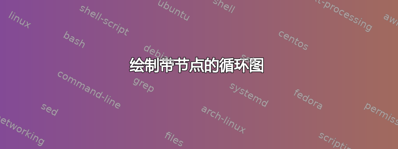
抱歉,您的问题不清楚。您的 MWE 与显示的图像不接近,您的问题描述不清楚。因此,看看以下 MWE(基于猜测和我对类似问题的回答)是否给出了您想要的结果:
\documentclass[border=3mm, tikz]{standalone}
\usetikzlibrary{arrows.meta,
                chains,
                positioning,
                quotes,
                shapes.geometric}

\begin{document}
%---------------------------------------------------------------%
% based on:
% http://tex.stackexchange.com/questions/300759/write-easily-a-tikz-flowchart/300829#300829
%---------------------------------------------------------------%
    \begin{tikzpicture}[
    node distance = 6mm and 18mm,
      start chain = A going below,
%
   arr/.style = {-Straight Barb, semithick},
  base/.style = {draw, minimum width=32mm, minimum height=8mm,
                 align=center, on chain=A, join=by arr},
startstop/.style = {base, rounded corners, fill=red!30},   % <---
  process/.style = {base, fill=orange!30},                 % <---
       io/.style = {base, trapezium, trapezium stretches body,
                    trapezium left angle=70, trapezium right angle=110,
                    fill=blue!30},
 decision/.style = {base, diamond, fill=green!30},
every edge quotes/.style = {auto=right, font=\small}
                    ]
\node [startstop]       {input};            % <-- A-1
\node [process]         {Loop start};
\node [process]         {1};
\node [process]         {2};
\node [decision]        {Yes or No ?};
\node [startstop]       {Stop};              % <-- A-6
%%
\draw[arr]  (A-5.west)  to ["No"] ++ (-1.8,0) |- (A-2); % feedback loop
\path       (A-5)       to ["Yes"]  (A-6);
    \end{tikzpicture}
\end{document}

答案2
好的,添加了 [xshift=7mm] 并且现在可以工作了:
\draw [arrow] (dec1) -- node[anchor=north] {Yes} ([xshift=7mm] dec1.east) -- ([xshift=7mm] pro1.east) -- (pro1);

但这是最好的方法吗?