

默认情况下,使用绘制的图表中的所有光纤pst-optexp都显示为黑色,除非明确设置颜色,如示例所示
\begin{pspicture}(18,6)
    \psset[optexp]{fiber=none, usefiberstyle}
    %\newpsstyle{Fiber}{linecolor=orange, linewidth=2\pslinewidth}
    \newpsstyle{Fiber}{linewidth=2\pslinewidth}
    \pnodes(1.5, 4){LaserIn}(2, 4){LaserOut}
    \pnodes(1.5, 2){SESAMIn}(2, 2){SESAMOut}
    \pnodes(4, 4){InputIsolatorIn}(5, 4){InputIsolatorOut}
    \pnodes(6.5, 2){PolarizerIn}(7.5, 2){PolarizerOut}
    \pnodes(9, 4){TSFIn}(11, 4){TSFOut}
    \pnodes(14, 3){LoopIn}(14, 2){LoopOut}
    \pnodes(10, 1){OutputIsolatorIn}(12,1){OutputIsolatorOut}
    \pnodes(16, 1){LaserOutLow}
    \optdiode[compname=PumpDiode, position=start](LaserIn)(LaserOut){\begin{tabular}{@{}c@{}}Laser\\diode\end{tabular}}
    \optisolator[compname=InputIsolator](InputIsolatorIn)(InputIsolatorOut){Pump Isolator}
    \optfiber[compname=ActiveFiber, position=start, linecolor=red](TSFIn)(TSFOut){Active fiber}

    \nput{75}{LaserOutLow}{Laser output}

    \drawfiber{InputIsolator}{ActiveFiber}
    \drawfiber{PumpDiode}{InputIsolator}
    \drawfiber{ActiveFiber}(LaserOutLow)
\end{pspicture}
结果是
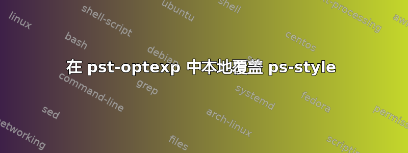
 另一方面,当删除第三行的注释时,我会得到
 尽管我明确设置了活动光纤的光纤颜色,但整个光纤仍为橙色。因此,我假设全局设置将始终覆盖光纤颜色的本地设置。这样对吗?或者我仍然可以使用全局光纤颜色并在本地覆盖它吗?
答案1
一般来说应该允许你使用本地样式。然而,这方面usefiberstyle=false似乎比较特殊。但你可以使用在本地更改光纤线样式,或者覆盖它:\optfiberaddtoFibernewFiber
\optfiber[compname=ActiveFiber, position=start, addtoFiber={linecolor=red}](TSFIn)(TSFOut){Active fiber}
完整示例:
\documentclass{standalone}
\usepackage{pst-optexp}
\begin{document}
\begin{pspicture}(18,6)
    \psset[optexp]{fiber=none}
    \newpsstyle{Fiber}{linecolor=orange, linewidth=2\pslinewidth}
    \pnodes(1.5, 4){LaserIn}(2, 4){LaserOut}
    \pnodes(1.5, 2){SESAMIn}(2, 2){SESAMOut}
    \pnodes(4, 4){InputIsolatorIn}(5, 4){InputIsolatorOut}
    \pnodes(6.5, 2){PolarizerIn}(7.5, 2){PolarizerOut}
    \pnodes(9, 4){TSFIn}(11, 4){TSFOut}
    \pnodes(14, 3){LoopIn}(14, 2){LoopOut}
    \pnodes(10, 1){OutputIsolatorIn}(12,1){OutputIsolatorOut}
    \pnodes(16, 1){LaserOutLow}
    \optdiode[compname=PumpDiode, position=start](LaserIn)(LaserOut){\begin{tabular}{@{}c@{}}Laser\\diode\end{tabular}}
    \optisolator[compname=InputIsolator](InputIsolatorIn)(InputIsolatorOut){Pump Isolator}
    \optfiber[compname=ActiveFiber, position=start, addtoFiber={linecolor=red}](TSFIn)(TSFOut){Active fiber}

    \nput{75}{LaserOutLow}{Laser output}

    \drawfiber{InputIsolator}{ActiveFiber}
    \drawfiber{PumpDiode}{InputIsolator}
    \drawfiber{ActiveFiber}(LaserOutLow)
\end{pspicture}
\end{document}
