


circuitikz我已经在绘制美观的单线图方面取得了很大进步。但仍有几点可以改进。
这是我目前的结果(代码添加在下面。)这个例子可能有点混乱,但以后删除不需要的元素会更容易:

以下方面可以改进:
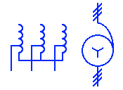
delta,wye符号zig太小,粗细不一致,与vco- 没有三相自耦变压器符号(右侧符号旋转 +j,并且没有三线符号)
- 长度
busbars为 0.3 的标签可以作为符号包含在内 - 这些
osourcetrans符号应该按比例放大 1/0.55 以与其他符号保持一致(我仍然需要在源代码中实现这一点) - 标签
osourcetrans位置不正确,可以改进为包含多行,如所示 - 接地符号:
psolid,pres,pimp,parc,ssolid,sres或simp可sarc添加
任何建议都将受到赞赏。
\documentclass[beamer]{standalone}
\usepackage{tikz}
\def\pgfsysdriver{pgfsys-dvipdfm.def}
%
\usepackage{pgfplots}
\usepackage[siunitx,european,oldvoltagedirection]{circuitikz}
\usepackage{xspace}
\usepackage{comment}


%\renewcommand*\familydefault{\sfdefault} %% Only if the base font of the document is to be sans serif
\usepackage[T1]{fontenc}
\usepackage{lmodern}
\usepackage{bm}

\usepackage{amsmath}
\usepackage{steinmetz}
\usepackage{pgf,siunitx}
\sisetup{output-decimal-marker = {,}
,separate-uncertainty}
\SendSettingsToPgf
%
\usepackage{relsize}


%\usepackage{longtable}
%\usepackage{lscape}


\usepackage[iso,english]{isodate}
%\renewcommand*\date[1]{{\isodate{#1}}}

\usepackage{steinmetz}% for \phasor{t}

\usepackage[UKenglish]{babel}


\pgfplotsset{width=11cm, height=6cm, compat = 1.7}
\usetikzlibrary{calc,angles,quotes}
\makeatother
\usepackage[subpreambles=true]{standalone}
\usepackage{import}

\begin{document}
{\hfill\small\begin{circuitikz}[style={european resistor, resistors/scale=0.55, inductors/scale=0.55, blocks/scale=0.5, grounds/scale=0.55}]
 \draw (0,0)
 to [vco,-,v>=\SI{24}{kV},l=$G$] ++(1,0)
 to[oosourcetrans,name=t1,prim=delta,sec=wye,-,] ++(1.5,0)
 -- ++(0,0.6)
 to [L,-,l=$Z_1$] ++(1,0)
 to [L,-,l=$Z_2$] ++(1,0)
 -- ++(0,-0.6)
 to[oosourcetrans,name=t2,prim=wye,sec=zig,-,] ++(1.5,0)
 to [L,-,l=$Z_c$] ++(1,0)
 to[oosourcetrans,name=t3,prim=delta,sec=wye,-,] ++(1.5,0)
 to [R,-,l=$R_\text{load}$,] ++(1,0)
 ;
 % fixing the labels of oosourcetrans to correct the distance from the symbol
 \draw (t1.90) ++(0,0.15) node {\shortstack{$T_1$\\$_{24:132}$}};
 \draw (t2.90) ++(0,0.15) node {\shortstack{$T_2$\\$_{132:12}$}};
 \draw (t3.90) ++(0,0.15) node {\shortstack{$T_3$\\$_{12:\num{0.4}}$}};
 % add the correct earthing symbols to the oosourcetrans
 \draw (t1.-70)  ++(0,0.2) node[ground]{};
 \draw (t2.-70)  ++(0,0.2) to [R,-,resistors/scale=0.3,l={\scriptsize \SI{1.5}{\kilo\ampere}}] ++(0,-0.6) node[tlground]{};
 \draw (t2.-110)  ++(0,0.2) node[ground]{};
 \draw (t3.-70)  ++(0,0.2) node[ground]{};
% draw and label busbars (busbars are vertical with length = 0.6)
 \draw [ultra thick] (2.5,-0.9) -- ++(0,1.8)node [anchor=south] {$gs_1$}; % generation station busbar
 \draw [ultra thick] (3.5,0.3) -- ++(0,0.6)node [anchor=south] {$ts_1$}; % transmission station busbar
 \draw [ultra thick] (4.5,-0.9) -- ++(0,1.8)node [anchor=south] {$ds_1$}; % transmission station busbar
 \draw [ultra thick] (6,-0.3) -- ++(0,0.6) node [anchor=south] {$ds_2$}; % distribution station busbar
 \draw [ultra thick] (7,-0.3) -- ++(0,0.6) node [anchor=south] {$ms_1$}; % minisub
 \draw (2.5,-0.6) to [L,-,l=$Z_3$, v=$\Delta U_t$] ++(2,0);
\end{circuitikz}\hfill~}
\end{document}
答案1
好的,我会尽力回答其中的一些问题。让我们从问题列表开始(下次,请在每个帖子中提出一个问题)。
- 是的,确实如此 --- 我会联系作者,看看我们是否可以为此添加一个开关/参数(更新:它将出现在下一版本中)。现在,我建议对这些符号进行暴力破解。
- 您可以在https://github.com/circuitikz/circuitikz/issues,并参考印刷品,也许有人会这样做(或者你可以尝试一下!我们会欢迎你的!)
- 我建议使用宏,例如https://tex.stackexchange.com/a/597815/38080,但
bus如果您更喜欢该to语法,我在这里提供了一个元素。 - 您正在使用非标准方式设置相对大小,请重试!
- 我提供了两个定位多行标签的示例,可以使用提供的
l2工具,也可以使用\shortstack并调整距离; - 我不知道所有这些“地面风格”是怎样的。请参阅第 2 点。
现在,代码执行以下操作(我已在其中添加了注释;请注意这是最小例如,这样我就可以继续工作,而不会产生大量的重复和分散注意力的事情......)
\pgf@circ@delta它开始修补用于绘制变压器符号的命令等。您可以pgfcircbipoles.tex在发行版中找到它们。前三个命令将线宽重置为电路的标准线宽,后三个命令稍微改变尺寸。我将公交车定义为非常挤压的
fullgeneric,其参数为高度,默认值为3(您可以更改此值;数字都与标准长度成比例)如果您不想要极点,则不需要
-在每个to命令中使用,它是默认的。有两种方法可以定位标签;使用
l2更加宽敞(并且在我看来可读性更高),使用\stackengine更加紧凑 --- 我想,这是一个品味问题。
\documentclass[border=10pt]{standalone}
\usepackage[siunitx, RPvoltages]{circuitikz}
\usepackage{etoolbox}

\makeatletter
% This should probably be added as a couple of parameters; I'll contact the author
% (see https://github.com/circuitikz/circuitikz/pull/397). But for now, let's just patch
% patching linewidth
\patchcmd{\pgf@circ@delta}
    {\pgf@circ@setlinewidth{bipoles}{\pgfstartlinewidth}}
    {\pgfsetlinewidth{\pgfstartlinewidth}}
    {}{\FAIL}
\patchcmd{\pgf@circ@zig}
    {\pgf@circ@setlinewidth{bipoles}{\pgfstartlinewidth}}
    {\pgfsetlinewidth{\pgfstartlinewidth}}
    {}{\FAIL}
\patchcmd{\pgf@circ@wye}
    {\pgf@circ@setlinewidth{bipoles}{\pgfstartlinewidth}}
    {\pgfsetlinewidth{\pgfstartlinewidth}}
    {}{\FAIL}
% patching scale
\patchcmd{\pgf@circ@delta}{-.01}{-.02}{}{\FAIL}
\patchcmd{\pgf@circ@wye}{-.015}{-.02}{}{\FAIL}
\patchcmd{\pgf@circ@zig}{-.015}{-.02}{}{\FAIL}
\makeatother

% define the bus (ab-)using the fullgeneric component
%
\tikzset{bus/.style={fullgeneric, %
        bipoles/fullgeneric/width=0.02, bipoles/fullgeneric/height=#1
    },
    bus/.default=3
}
\begin{document}
\begin{circuitikz}[european] % do not use style={}!
    % this is the correct way to set the class values
    \ctikzset{resistors/scale=0.55, inductors/scale=0.55,
         blocks/scale=0.5, grounds/scale=0.55}
    \draw (0,0)
    % choose one of the following two
    % to[oosourcetrans, name=t1, prim=delta, sec=wye,
    %     l=\shortstack{$T_1$\\${}_{24:132}$}, label distance=-6pt] ++(3,0)
    to[oosourcetrans, name=t1, prim=delta, sec=wye,
        l2=$T_1$ and {\scriptsize 24:132}, l2 halign=c] ++(3,0)
    to[bus, l=$gs_1$, name=gs1] ++(1,0)
    (gs1.center) ++(0, 0.6) to [L,l=$Z_1$] ++(2,0)
    to [bus=1, l=$ts_1$] ++(1,0);
\end{circuitikz}
\end{document}

PS 您可以注意到为什么我更喜欢总线的宏:使用宏,如链接的帖子中所示,总线的宽度为零,因此总线之间的组件自然居中。如果您使用to[bus...,组件的大小与路径相同,您必须自己考虑距离,并且必须管理引线。如果您使用中的定义https://tex.stackexchange.com/a/597815/38080,电路将是:
\begin{circuitikz}[european] % do not use style={}!
    % this is the correct way to set the class values
    \ctikzset{resistors/scale=0.55, inductors/scale=0.55,
        blocks/scale=0.5, grounds/scale=0.55}
    \draw (0,0)
    % choose one of the following two
    % to[oosourcetrans, name=t1, prim=delta, sec=wye,
    %     l=\shortstack{$T_1$\\${}_{24:132}$}, label distance=-6pt] ++(3,0)
    to[oosourcetrans, name=t1, prim=delta, sec=wye,
        l2=$T_1$ and {\scriptsize 24:132}, l2 halign=c] ++(3,0)
    \bushere{1.5}{$gs_1$}{}
    ++(0, 0.6) to [L,l=$Z_1$] ++(2,0)
    \bushere{0.5}{$ts_1$}{};
\end{circuitikz}
结果如下:

PPS 是的,这些总线有点不对称。这是因为有一个错误,\bushere为上面的标签腾出了空间……解决方案(其中任何一个)留给学生!