

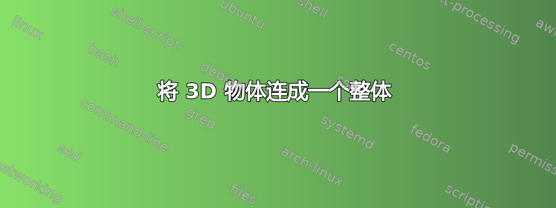
这里是制作一些 3d 对象的好方法,但我找不到将两个 3d 对象连接成一个像这样的对象的方法(如果知道如何添加带有数字的箭头就好了):

这是到目前为止我尝试过的 MWE(刚刚复制代码并删除了一些部分)。我不知道如何旋转它们,也不知道如何绘制半圆柱体。我甚至不知道这是否是正确的方向。但主要的问题是连接 3d 对象,如果可能的话。
\documentclass[11pt]{scrartcl}
\PassOptionsToPackage{dvipsnames,svgnames}{xcolor}
\usepackage{xkeyval,tkz-base}
\usetikzlibrary{arrows,calc}
 \makeatletter%

\define@cmdkey[TKZ]{ell}{color}{}
\define@cmdkey[TKZ]{ell}{shift}{}
\presetkeys[TKZ]{ell}{color = {},shift = 0}{}

\newcommand*{\ellipseThreeD}[1][]{\tkz@ellipseThreeD[#1]}%
\def\tkz@ellipseThreeD[#1](#2,#3)(#4,#5){%
\setkeys[TKZ]{ell}{#1}%
  \draw[yshift=\cmdTKZ@ell@shift cm,dashed] (#4,0) arc(0:180:#4 and #5);
  \draw[yshift=\cmdTKZ@ell@shift cm ] (-#4,0) arc(180:360:#4 and #5);
  \path[fill=\cmdTKZ@ell@color,opacity=0.5,shade](#2 cm,#3 cm) ellipse (#4 and #5);
}

\def\tkzCone{\pgfutil@ifnextchar[{\tkz@cone}{\tkz@cone[]}}
\def\tkz@cone[#1]#2#3#4{%

\pgfmathsetmacro{\bb}{#2*#3}
\pgfmathsetmacro{\yy}{\bb*\bb/#4}
\pgfmathsetmacro{\xx}{#2*sqrt((1-\yy)/#4)}
\fill[color=Maroon!10] (0,#4)--(-\xx,\yy)  arc(180:360:\xx cm and .5 cm);
\ellipseThreeD[color=Maroon!30](0,0)(\xx cm,.5 cm)
\draw (0,#4)--(\xx,\yy);
\draw (0,#4)--(-\xx,\yy);
}%

\def\tkzCylinder{\pgfutil@ifnextchar[{\tkz@cylinder}{\tkz@cylinder[]}}
\def\tkz@cylinder[#1]#2#3#4{%
\pgfmathsetmacro{\bb}{#2*#3}
\pgfmathsetmacro{\yy}{\bb*\bb/#4}
\pgfmathsetmacro{\xx}{#2*sqrt((1-\yy)/#4)}
  \fill[color=Maroon!10] (-\xx cm,0)--(-\xx cm,#4 cm)
         arc(180:360:\xx cm and .5 cm)--(\xx cm,0)
         arc(360:180:\xx cm and .5 cm);
\ellipseThreeD[color=Maroon!30](0,0)(\xx cm,.5 cm)
\begin{scope}[yshift=#4 cm]
  \draw[fill=\cmdTKZ@ell@color,opacity=0.5,shade](0,0) ellipse (\xx cm and .5 cm) ;
\end{scope}
\draw (\xx cm,0)--(\xx cm,#4 cm);
\draw (-\xx cm,0)--(-\xx cm,#4 cm);
}%

\begin{document}

 \tikz  \tkzCone{3}{0}{5};
  \hspace{1cm}
 \tikz   \tkzCylinder{3}{0}{5};

\end{document}
它产生了这个:

答案1
我可能会像这样画(感谢这个答案有关如何计算临界角的提示):
\documentclass[border=10pt]{standalone}
\usepackage{tikz}

\begin{document}

\begin{tikzpicture}[>=stealth, line join=round, line cap=round]

% define tilt angle
\pgfmathsetmacro{\TiltAngle}{20}

% CONE
% calculate critical angle where tangentials intersect ellipsis
\pgfmathsetmacro{\ConeHeight}{3.06}
\pgfmathsetmacro{\ConeRadius}{1.4}
\pgfmathsetmacro{\CritAngle}{acos((\ConeRadius/2)/\ConeHeight)}

% draw tangentials
\draw[thick, orange, fill=orange!10]
    ({180-\CritAngle}:{\ConeRadius/2} and {\ConeRadius})
        -- ({-\ConeHeight},0) coordinate (A)
        -- ({180+\CritAngle}:{\ConeRadius/2} and {\ConeRadius});
% draw visible part of base
\draw[thick, orange, fill=orange!20]
    (270:{\ConeRadius/2} and {\ConeRadius}) coordinate (B)
        arc[start angle=270, end angle=\TiltAngle,
            x radius={\ConeRadius/2}, y radius={\ConeRadius}];
\coordinate (E) at (90:{\ConeRadius/2} and {\ConeRadius});

% HALF CYLINDER
\pgfmathsetmacro{\CylinderHeight}{2.2}

% draw base
\draw[thick, orange, fill=orange!20]
    ([shift={(right:\CylinderHeight)}]\TiltAngle:{\ConeRadius/2} and {\ConeRadius})
        arc[start angle={\TiltAngle}, end angle={-(180-\TiltAngle)},
            x radius={\ConeRadius/2}, y radius={\ConeRadius}];
% draw bottom part
\draw[thick, orange, fill=orange!10]
    ({180+\TiltAngle}:{\ConeRadius/2} and {\ConeRadius})
        arc[start angle={180+\TiltAngle}, end angle=270,
            x radius={\ConeRadius/2}, y radius={\ConeRadius}]
        -- ++(\CylinderHeight,0) coordinate (C)
        arc[start angle=270, end angle={180+\TiltAngle},
            x radius={\ConeRadius/2}, y radius={\ConeRadius}];
% draw cut surface
\draw[thick, orange, fill=orange!10]
    (\TiltAngle:{\ConeRadius/2} and {\ConeRadius})
        -- ({180+\TiltAngle}:{\ConeRadius/2} and {\ConeRadius})
        -- ++(\CylinderHeight,0)
        -- ([shift={(right:\CylinderHeight)}]\TiltAngle:{\ConeRadius/2} and {\ConeRadius})
        -- cycle;

% draw hidden part of cone base
\draw[densely dashed, orange]
    (270:{\ConeRadius/2} and {\ConeRadius})
        arc[start angle=-90, end angle=\TiltAngle,
            x radius={\ConeRadius/2}, y radius={\ConeRadius}];

% AXIS
\draw[densely dashed, orange] ({-\ConeHeight-0.25},0) -- ({\CylinderHeight+0.5},0);

% ANNOTATIONS
\draw (A) -- ({-\ConeHeight},-2) coordinate (a);
\draw (B) -- (0,-2) coordinate (b);
\draw (C) -- (\CylinderHeight,-2) coordinate (c);
\draw (C) -- (C -| {\ConeHeight+0.5},0) coordinate (d);
\draw (E) -- (E -| {\ConeHeight+0.5},0) coordinate (e);

\draw[<->] ([yshift=5pt]a) -- ([yshift=5pt]b) node[midway, below] {30,6};
\draw[<->] ([yshift=5pt]b) -- ([yshift=5pt]c) node[midway, below] {22};
\draw[<->] ([xshift=-5pt]d) -- ([xshift=-5pt]e) node[midway, right] {28};

\end{tikzpicture}

\end{document}

答案2
我的 Asymptote 代码只使用拉伸命令。第一个底面b1是圆形,挤压后会形成水平圆锥体,而第二个底面b2是半个圆形,挤压后会形成水平半圆柱体

// http://asymptote.ualberta.ca/
unitsize(2mm);
import three;
currentprojection=orthographic(3,1,.6,center=true,zoom=.8);
pen p=yellow;
real r=14;
real y1=30.6,y2=22;
triple V1=(0,-y1,0),V2=(0,y2,0);
path3 b1=circle(O,r,normal=Y);
path3 b2=arc(O,(r,0,0),(-r,0,0),normal=Y)--cycle;
draw(extrude(b1,V1--cycle),p);
draw(extrude(b2,V2),p);