

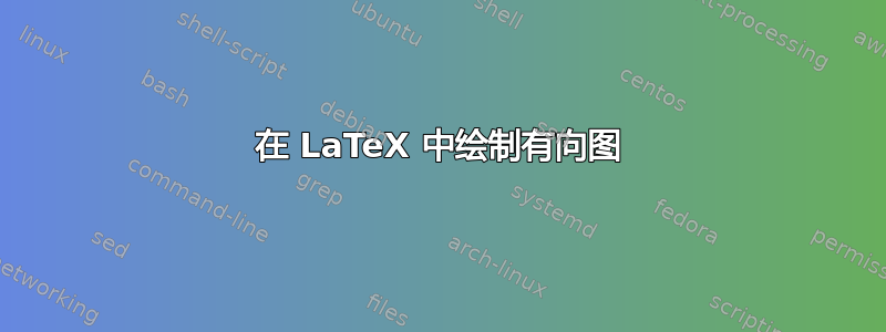
我的目标是绘制下图:
 我尝试用TikZ包编写代码,但最终的图形如下:
 其代码为:
其代码为:
\documentclass{standalone}

\usepackage{tikz}

\usetikzlibrary{decorations.pathreplacing,decorations.markings}
\usetikzlibrary{arrows,automata}
\usetikzlibrary{calc}

\tikzset{dot/.style =
{circle,
draw=blue,
line width=.5pt},
dot/.default = 4pt
}

\tikzset{
  % style to apply some styles to each segment of a path
  on each segment/.style={
    decorate,
    decoration={
      show path construction,
      moveto code={},
      lineto code={
        \path [#1]
        (\tikzinputsegmentfirst) -- (\tikzinputsegmentlast);
      },
      curveto code={
        \path [#1] (\tikzinputsegmentfirst)
        .. controls
        (\tikzinputsegmentsupporta) and (\tikzinputsegmentsupportb)
        ..
        (\tikzinputsegmentlast);
      },
      closepath code={
        \path [#1]
        (\tikzinputsegmentfirst) -- (\tikzinputsegmentlast);
      },
    },
  },
  % style to add an arrow in the middle of a path
  mid arrow/.style={postaction={decorate,decoration={
        markings,
        mark=at position .5 with {\arrow[#1]{stealth}}
      }}},
}

\begin{document}


\begin{tikzpicture}
  % Axes
%\draw[help lines, color=gray!30, dashed] (-7, -7) grid (7, 7);
%\draw[->,ultra thick] (-7,0)--(7,0) node[right]{$x$};
%\draw[->,ultra thick] (0, -7)--(0, 7) node[above]{$y$};

  % First, define nodes
  \draw (-5, 0) node[
                            circle,
                            inner sep=0pt,
                            fill=black,
                            label={left:{$A$}}
                            ] (A) {};
  \draw (-2, 2) node[
                            circle,
                            inner sep=0pt,
                            fill=black,
                            label={above:{$B$}}
                            ] (B) {};
  \draw (2, 2) node (C) {$C$};
  \draw (5, 0) node (D) {$D$};
  \draw (2, -2) node (E) {$E$};
  \draw (-2, -2) node (F) {$F$};

  % Draw curved path
  \path [thick, draw=black, postaction={very thick, on each segment={mid arrow=black}}]
  (A) to [bend left] (B)
  (A) to [bend right] (B)
  (B) to [bend left] (C)
  (B) to [bend right] (C)
  (C) to [bend left] (D)
  (C) to [bend right] (D)
  (E) to [bend left] (D)
  (E) to [bend right] (D)
  (E) to (D)
  (F) to [bend left] (E)
  (F) to [bend right] (E)
  (F) to (E)
  (A) to [bend left] (F)
  (A) to [bend right] (F)
  (A) to (F);
\end{tikzpicture}

\end{document}
怎样改才能画出上图的样子?
答案1
真的没有理由让事情变得过于复杂。
\documentclass[tikz, border=1cm]{standalone}
\usetikzlibrary{decorations.markings, arrows.meta}
\tikzset{
mid arrow/.style={postaction={decorate, decoration={
markings,
mark=at position .5 with {\arrow{Straight Barb}}
}}},
}

\begin{document}
\begin{tikzpicture}
\node[inner sep=2pt, circle] (A) at (-5,0) {$A$};
\node[inner sep=2pt, circle] (B) at (-2,2) {$B$};
\node[inner sep=2pt, circle] (C) at (2,2) {$C$};
\node[inner sep=2pt, circle] (D) at (5,0) {$D$};
\node[inner sep=2pt, circle] (E) at (2,-2) {$E$};
\node[inner sep=2pt, circle] (F) at (-2,-2) {$F$};

\draw[thick, mid arrow] (A.north east) to[bend left] (B.south west);
\draw[thick, mid arrow] (A.north east) to[bend right] (B.south west);
\draw[thick, mid arrow] (B.east) to[bend left] (C.west);
\draw[thick, mid arrow] (B.east) to[bend right] (C.west);
\draw[thick, mid arrow] (C.east) to[bend left] (D.north west);
\draw[thick, mid arrow] (C.east) to[bend right] (D.north west);
\draw[thick, mid arrow] (A.south east) to[bend left] (F.north west);
\draw[thick, mid arrow] (A.south east) to[bend right] (F.north west);
\draw[thick, mid arrow] (A.south east) to (F.north west);
\draw[thick, mid arrow] (F.east) to[bend left] (E.west);
\draw[thick, mid arrow] (F.east) to[bend right] (E.west);
\draw[thick, mid arrow] (F.east) to (E.west);
\draw[thick, mid arrow] (E.east) to[bend left] (D.south west);
\draw[thick, mid arrow] (E.east) to[bend right] (D.south west);
\draw[thick, mid arrow] (E.east) to (D.south west);

\end{tikzpicture}
\end{document}

答案2
只需用节点内部的字母命名节点,不要使用带标签的坐标,然后您可以将每个节点(及其名称)用作连接的一部分(A) -- (B),TikZ 会自行找到其边界上的点。它对bend left和执行相同的操作bend right,但使用边界上除直线部分以外的其他点。
但是使用正常(未绘制)--路径,您可以轻松找到节点边界上的点并保存它们。(当然,我们也可以计算角度或手动指定锚点)。
我给第一个节点一个别名,G以便可以在循环中简单地访问它。
LaTeX 函数\@Alph有助于将数字 ( \cnt) 转换为字母。我们还可以使用数字而不是字母来命名节点,这会使这更容易一些。对于超过 26 个节点,您将需要另一种方法来命名节点。
我正在使用最新版本arrows.meta图书馆并且它的Stealth箭头不需要额外的缩放。如果您想要另一个箭头,您可以选择您想要的箭头,该库提供了多种笔尖样式。
代码
\documentclass{standalone}
\usepackage{tikz}
\usetikzlibrary{decorations.markings}
\usetikzlibrary{arrows.meta}
\tikzset{% style to add an arrow in the middle of a path
  mid arrow/.style={postaction={decorate,decoration={
        markings,
        mark=at position .5 with {\arrow[#1]{Stealth}}}}}}
\makeatletter
\newcommand*\intToChar[1]{\@Alph{#1}}
\makeatother
\begin{document}

\begin{tikzpicture}
% Axes
%\draw[help lines, color=gray!30, dashed] (-7, -7) grid (7, 7);
%\draw[->,ultra thick] (-7,0)--(7,0) node[right]{$x$};
%\draw[->,ultra thick] (0, -7)--(0, 7) node[above]{$y$};

% First define nodes
\foreach[count=\cnt] \pnt/\lab in {(-5, 0)/A,
                                   (-2, 2)/B,
                                   ( 2, 2)/C,
                                   ( 5, 0)/D,
                                   ( 2,-2)/E,
                                   (-2,-2)/F}
  \node (\lab) at \pnt {$\lab$};
\path node also [alias=G] (A);

% Find points on their border to the other nodes
\foreach \lab[count=\cnt from 2] in {A, ..., F}
  \path (\lab) -- coordinate[at start] (\lab-to-\intToChar{\cnt})
                  coordinate[at end]   (\intToChar{\cnt}-to-\lab)
                  (\intToChar{\cnt});

% Draw the lines and curves
\path [thick, every edge/.append style={mid arrow}]
  foreach \A/\B in {A/B, B/C, C/D, G/F, F/E, E/D} {
   (\A-to-\B) edge [bend left] (\B-to-\A)
              edge [bend right] (\B-to-\A)
  }
  foreach \A/\B in {G/F, F/E, E/D} {
    (\A) edge (\B)
  }
  ;
\end{tikzpicture}
\end{document}
输出
