

我正在尝试使用以下方法重新创建包含加热元件的电路图电路图但在绘制元素本身时遇到了麻烦。
我尝试使用spring第 4.7 节中的形状电路图手册,并且我也尝试过使用snakeTikZ 中的路径装饰,但两者都无法获得合理的结果。
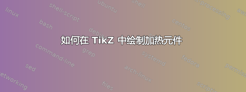
我想知道是否有人能帮我指出绘制下图所示形状的正确方向,或者提供一个我可以改编用于我自己的文档的示例。代码不需要生成相同的图形;任何包含这种 U 形路径中的蛇形线的类似图形都可以。

答案1
这可能需要自己绘制解决方案。这可以通过decorations.pathreplacing库使用show path construction和定义从起点到终点的新路径来完成。
在下面的代码中,您可以从一个坐标到另一个坐标绘制一个加热元件,并将元件的方向指定为一个角度(默认值=90)。例如,\draw[htr] (blk1)--(red1);对于第一幅图像和\draw[htr=0] (red2)--(blk2);第二幅图像。

\documentclass{article}

\usepackage{tikz}
\usetikzlibrary{decorations.pathreplacing}

\tikzset{
    htr/.style={decoration={show path construction,
        lineto code={\draw[looseness=1.3] (\tikzinputsegmentfirst)node[dot]{}
            to[out=#1, in=#1+180] ++(#1-45:.3) to[out=#1, in=#1+180] ++(#1+45:.3)
            to[out=#1, in=#1+180] ++(#1-45:.3) to[out=#1, in=#1+180] ++(#1+45:.3)
            to[out=#1, in=#1+180] ++(#1-45:.3) to[out=#1, in=#1+180] ++(#1+45:.3)
            to[looseness=.7,out=#1, in=#1]
            ([shift={(#1:1.8/sqrt(2))}]\tikzinputsegmentlast)
            to[out=#1+180, in=#1] ++(#1+135:.3) to[out=#1+180, in=#1] ++(#1+225:.3)
            to[out=#1+180, in=#1] ++(#1+135:.3) to[out=#1+180, in=#1] ++(#1+225:.3)
            to[out=#1+180, in=#1] ++(#1+135:.3) to[out=#1+180, in=#1] (\tikzinputsegmentlast)node[dot]{};
        }}, decorate},
    htr/.default=90,
    dot/.style={circle, fill, inner sep=1pt, outer sep=0}
}

\begin{document}

\begin{tikzpicture}[font=\sffamily]
\draw (0,0)--node[sloped, above, near end]{BLK}++(0,2)coordinate(blk1);
\draw (.8,0)--node[sloped, above, near end]{RED}++(0,2)coordinate(red1);
\draw[htr] (blk1)--(red1);

\draw (1,0)--node[sloped, above, near end]{BLK}++(2,0)coordinate(blk2);
\draw (1,.8)--node[sloped, above, near end]{RED}++(2,0)coordinate(red2);
\draw[htr=0] (red2)--(blk2);
\end{tikzpicture}

\end{document}
答案2
这种形状可能需要一个“真实”的组件。一个近似值可以是装饰:
\documentclass[border=10pt]{standalone}
\usepackage[T1]{fontenc}
\usepackage[siunitx, RPvoltages]{circuitikz}
\usetikzlibrary{decorations, decorations.pathmorphing}
\usetikzlibrary{decorations}
\begin{document}
\begin{tikzpicture}
    \coordinate(A) at (0,0); \coordinate(B) at (1,0);
    \node [circ, label=below:A] at (A){};
    \node [circ, label=below:B] at (B){};
    %\draw [red] (A) -- ++(0,3) -| (B);
    \begin{scope}[every path/.style={%
        decorate, decoration={coil, segment length=.4cm, aspect=0}}]
        \draw  (A) -- ++(0,3) coordinate(tmp);
        \draw  (tmp) -- (tmp-|B);
        \draw  (tmp-|B) -- (B) coordinate(tmp);
    \end{scope}
\end{tikzpicture}
\end{document}

...尽管我在装饰参数上遇到了很多困难;但我怀疑有一个奇怪的“特征”正在发生:
\documentclass[border=10pt]{standalone}
\usepackage{tikz}
\usetikzlibrary{decorations, decorations.pathmorphing}
\begin{document}
\begin{tikzpicture}[x=1cm]
    \draw[decorate,decoration={coil,aspect=0,segment length=0.4cm}] (0,3/2) -- ++(1,0);
    \draw[decorate,decoration={coil,aspect=0,segment length=0.5cm}] (0,2/2) -- ++(1,0);
    \draw[decorate,decoration={coil,aspect=0,segment length=0.8cm}] (0,1/2) -- ++(1,0);
    \draw[decorate,decoration={coil,aspect=0,segment length=1.0cm}] (0,0) -- ++(1,0);
\end{tikzpicture}
\end{document}
