

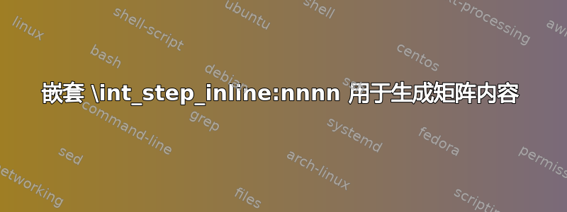
我想重现这里给出的绘图,这是我用 inkskape 做的。主要问题在于生成 expl3 中的项目的代码。我使用了\int_step_inline:nnnn嵌套的代码。一个是使用每行 1 到 10 个项目来填充行。第二个\int_step_inline:nnnn是传递到下一行。当我尝试解决问题时,我添加了一些内容来打印计数器的值。
\documentclass{beamer}
\mode<presentation>
{    \usetheme{metropolis}    }

\usepackage{fontsize,fix-cm,etoolbox}
\usepackage{tikz}
\usetikzlibrary{shapes,matrix}
\changefontsize[14.6]{12}

\tikzset{
  allmatrix/.style = {matrix of nodes,
                      nodes in empty cells,matrix anchor=#1,
                      every outer matrix/.append style={inner sep=+0pt, outer sep=0mm},
                      row sep=-\pgflinewidth, column sep=-\pgflinewidth,
                      ampersand replacement=\&, nodes={outer sep=0pt},
                      text height=1.5ex, text depth=.25ex},}
\ExplSyntaxOn
\NewDocumentCommand\rows { m m } {
  \int_new:N \l_tmpa
  \tl_clear_new:N #1
  \int_step_inline:nnnn { 0 } { 1 } { #2 }
  {
    \int_set:Nn \l_tmpa { ##1 }
%      \tl_put_right:Nn #1 { \node at (##1 *.5cm,0.3) [circle, draw] {##1 | \int_use:N \l_tmpa} ; }
    \int_step_inline:nnnn { 0 } { 1 } { \l_tmpa }
    {
      \tl_put_right:Nn #1 { \node at (##1 *.5cm,0) [circle, draw] {##1 | \int_use:N \l_tmpa} ; }
    }
    \tl_put_right:Nn #1 { \\ }
  }
}
\ExplSyntaxOff

\begin{document}
\begin{frame}
  \rows{\mystack}{4}

\begin{tikzpicture}
\matrix at (0,0)
    [shift={(0.5,-1.5)}, allmatrix=north west,]{
\mystack
  };
%  \shade (0,0) circle  (.2cm) [myball] ;
\end{tikzpicture}
\end{frame}
\end{document}
答案1
在内部循环中,您将需要使用####1循环计数器:
\NewDocumentCommand\rows { m m } {
  \int_new:N \l_tmpa
  \tl_clear_new:N #1
  \int_step_inline:nnnn { 0 } { 1 } { #2 } {
    \int_set:Nn \l_tmpa { ##1 }
    \int_step_inline:nnnn { 0 } { 1 } { \l_tmpa } {
      \tl_put_right:Nn #1 { \node at (####1 *.5cm,0) [circle, draw] {} ; }
    }
    \tl_put_right:Nn #1 { \\ }
  }
}
这是一个可以在 主体内部使用的实现\matrix。
为此,我们需要注意使用情况\pgfmatrixendrow(即\\),因为最后一个需要位于}矩阵关闭之前,以检测矩阵的正确结束。
这也是为什么其他\pgfmatrixendrows 出现在非第一行的每一行开头的原因。
放置矩阵后,的内容append after command将在行周围绘制圆角矩形,其中calc库用于绘制垂直分隔符。(我们保存\tikzlastnode,即矩阵节点的名称,因为\tln它被另一个节点/坐标覆盖之前。)
对于右侧部分的文本,我使用 PGFKeys.list处理程序(未分组的\foreach)来设置一些值键,然后我可以通过 检索这些值键\pgfkeysvalueof。\rows宏和setup language键都可以自定义,以允许使用两种以上的语言。
可能有一个解决方案,c3list但需要将其作为列表列表来处理才能正确检索值。
或者,内循环可以使用chains具有交替节点距离的 TikZ 库,也可以使用\int_if_odd:PGFMath 自己的isodd/ iseven。
####1但它不使用内部循环变量,而是使用chains库的\tikzchaincount变量(在我们的例子中等于####1)。
以下代码将在节点边界(而不是中心)之间交替设置 2mm 和 4mm 的空间。
\tikzset{Right/.style = { right = \int_if_odd:nTF { \tikzchaincount } { 4mm }{ 1mm } #1}}
\NewDocumentCommand { \rows } { m m } {
  \int_step_inline:nnnn { #1 } { 1 } { #2 } {
    \int_compare:nNnF { ##1 } = { #1 } { \pgfmatrixendrow }
    \tikzset{start~chain={\tikzmatrixname-##1-1}~going~Right}
    \int_step_inline:nnnn { 1 } { 1 } { ##1 } {
      \node [ball~node, on~chain] {};
    }
    \pgfmatrixnextcell
    \node [matrix~node] {\pgfkeysvalueof{/lang1/##1}};
    \pgfmatrixnextcell
    \node [matrix~node] {\pgfkeysvalueof{/lang2/##1}};
  }
  \pgfmatrixendrow
}
代码
\documentclass[tikz]{standalone}
\usetikzlibrary{calc, fit}
\ExplSyntaxOn
\NewDocumentCommand { \rows } { m m } {
  \int_step_inline:nnnn { #1 } { 1 } { #2 } {
    % no new row at the very first row
    \int_compare:nNnF { ##1 } = { #1 } { \pgfmatrixendrow }
    % for row ##1 draw ##1 balls
    \int_step_inline:nnnn { 1 } { 1 } { ##1 } {
      % this loop now uses ####1 as loop counter
      \node [ball~node] (\tikzmatrixname-##1-1-####1) % 1 is the column number
        % every ball's center is 6mm apart but each odd numbered ball is
        % shifted to the right, closer to the next one
        at (####1 * 6mm \int_if_odd:nT { ####1 } { +2mm }, 0) {};
    }
    \pgfmatrixnextcell
    \node[matrix~node] {\pgfkeysvalueof{/lang1/##1}};
    \pgfmatrixnextcell
    \node[matrix~node] {\pgfkeysvalueof{/lang2/##1}};
  }
}
\ExplSyntaxOff
\tikzset{
  setup language/.style={
    /utils/exec=\def\pgfmathcounter{0},
    /lang1/width/.initial=0pt, /lang2/width/.initial=0pt,
    /utils/temp/.style args={##1/##2}{
      /utils/exec=\edef\pgfmathcounter{\inteval{\pgfmathcounter+1}},
      /lang1/width/.evaluated={max(\pgfkeysvalueof{/lang1/width},width("##1"))},
      /lang2/width/.evaluated={max(\pgfkeysvalueof{/lang2/width},width("##2"))},
      /lang1/\pgfmathcounter/.initial={##1},
      /lang2/\pgfmathcounter/.initial={##2}},
    /utils/temp/.list={#1}}}
\begin{document}
\begin{tikzpicture}[
  ball node/.style={shape=circle, shading=ball, ball color=red!90},
  matrix node/.style={
    anchor=mid,
    name=\tikzmatrixname-\the\pgfmatrixcurrentrow-\the\pgfmatrixcurrentcolumn},
  setup language={un/one, deux/two, trois/three, quatre/four, cinq/five,
                  six/six, sept/seven, huit/eight, neuf/nine, dix/ten}]
\matrix[
  row sep=5mm, column sep=5mm, align=left,
  column 2/.append style={text width=\pgfkeysvalueof{/lang1/width}},
  column 3/.append style={text width=\pgfkeysvalueof{/lang2/width}},
  append after command={
    % \tikzlastnode will be overwritten by the next coordinate/node
    % let's save it in \tln, this will hold the matrix's name
    \pgfextra{\let\tln\tikzlastnode}
    foreach \row in {1,...,10}{
      node[rounded corners, outer sep=+0pt, draw,
        fit=(\tln-\row-1-1)(\tln-\row-3.east-|\tln.east)] (fit) {}
      foreach \coord in {($(\tln-\row-3)!.5!(\tln-\row-2)$),
                         ($(midway)!     2 !(\tln-\row-2)$)}{
        \coord coordinate (midway)
          (midway|-fit.north) edge (midway|-fit.south)}}}]{
  \rows{1}{10}
  % every matrix needs to end with \\ = \pgfmatrixendrow before closing brace
  % this can't be done be L3's loop
  \pgfmatrixendrow};
\end{tikzpicture}
\end{document}
输出

答案2
这是一个纯钛钾Z解决方案。希望它能有所帮助。
\documentclass[tikz,border=2mm]{standalone}

\begin{document}
\begin{tikzpicture}
\foreach[count=\ii]\i/\j in
{
  un/one,
  deux/two,
  trois/three,
  quatre/four,
  cinq/five,
  six/six,
  sept/seven,
  huit/eight,
  neuf/nine,
  dix/ten
}
{
  \begin{scope}[shift={(0,-\ii)}]
    \draw[rounded corners] (0,-0.3) rectangle (8,0.3);
    \foreach\k in {4,6}
      \draw (\k,-0.3) -- (\k,0.3);
    \node at (5,0) {\strut\i};
    \node at (7,0) {\strut\j};
    \foreach\k in {1,...,\ii}
      \fill[shading=ball,ball color=red] ({0.225*\k+0.225*int((\k+1)/2)},0) circle (0.1);
  \end{scope}
}

\end{tikzpicture}
\end{document}

答案3
这里我使用其他人介绍的一些内容来提供我的解决方案。它仍然需要改进。我必须找到 \tl_put_right:Nn 和 \tl_put_right:Nx 的替代方案。
\documentclass{beamer}
\mode<presentation>
{    \usetheme{metropolis}    }

\usepackage{fontsize,fix-cm}
\usepackage{tikz,calc}
\usetikzlibrary{shapes,matrix,calc}

\changefontsize[14.6]{12}

\tikzset{
  allmatrix/.style = {
  matrix of nodes,nodes in empty cells,
  matrix anchor=#1,
  every outer matrix/.append style={
  inner sep=+0pt, outer sep=0mm},
  row sep=-\pgflinewidth,
  column sep=-\pgflinewidth,
  ampersand replacement=\&,
  nodes={outer sep=0pt},text height=1.5ex,
  text depth=.25ex},}

\ExplSyntaxOn
\NewDocumentCommand\rows { m m m m m m } {
\clist_new:N \l_col_deux
\clist_new:N \l_col_trois

\clist_set:Nn \l_col_deux { #4 }
\clist_set:Nn \l_col_trois { #5 }

  \int_new:N \l_tmpa

  \dim_new:N \l_pos % horizontal position of next node
  \dim_zero:N \l_pos

  \dim_new:N \l_radius
  \dim_set:Nn \l_radius { 4pt }

  \dim_new:N \l_gap % gap between items
  \dim_set:Nn \l_gap { 2 \l_radius + 2pt }

  \dim_new:N \l_oddgap
  \tl_clear_new:N { #1 }
  \int_step_inline:nnnn { 1 } { 1 } { #2 }
  {
    \int_set:Nn \l_tmpa { ##1 }
    \dim_zero:N \l_pos
    \int_step_inline:nnnn { 1 } { 1 } { \l_tmpa }
    {
      \int_if_odd:nTF  { ####1 } { \dim_set:Nn \l_oddgap { 0pt } } { \dim_set:Nn \l_oddgap { 6pt } }
      \int_compare:nNnTF { ####1 } = { 1 } { \dim_zero:N \l_oddgap } { }
      \tl_put_right:Nn { #1 } { \shade }
      \tl_put_right:Nx { #1 } { [baseline=6pt, shading=ball]
      ( \dim_use:N \l_pos, \dim_use:N \l_radius) circle (\dim_use:N \l_radius); }
      \dim_add:Nn \l_pos { \l_gap + \l_oddgap }
    }
    \tl_put_right:Nx { #1 } { #6 \clist_item:Nn \l_col_deux { ##1 } %
                                 #6 \clist_item:Nn \l_col_trois { ##1 } #3 }
  }
}
\ExplSyntaxOff

\begin{document}
\begin{frame}
  \rows{\mystack}{10}{ \\ }
{un,deux,trois,quatre,cinq,six,sept,huit,neuf,dix}
{one,two,three,four,five,six,seven,heigh,nine,tex}{ \& }

  \newlength{\textcolumn}
  \settowidth{\textcolumn}{quatre}

  \begin{tikzpicture}[overlay, remember picture]
  \matrix at (current page.north) (items)
    [shift={(0.5,-1.5)}, allmatrix=north, row sep = 1mm,
    column sep=.5cm, nodes={text width=\textcolumn+4pt,align=left}]
  { \mystack };

\end{tikzpicture}
\end{frame}
\end{document}