

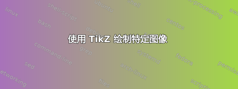
我想要绘制这个图像:
 我写了这段代码,但我无法根据节点 A1...A4 定义镜像节点。
如何根据 A1 ... A4 定义节点 B1 ... B4?
\documentclass[border=5pt]{standalone}

\usepackage{tikz}

\usepackage{amsmath,amsfonts,amssymb}

\begin{document}

\begin{tikzpicture}[line cap=round]

  % First, define nodes
\node[inner sep=0pt] (A1) at (0, 0) {};
\node[inner sep=0pt] (A2) at (1, 0) {};
\node[inner sep=0pt] (A3) at (1.5, 1.5) {};
\node[inner sep=0pt] (A4) at (-0.2, 1) {};

\draw [line width=2pt, -] (A1) -- (A2) -- (A3) -- (A4) -- (A1);

\end{tikzpicture}

\end{document}
答案1
使用 areflection和宏,\tkzDefPointsBy您可以轻松定义 $B1、B2、B3、B4$。您可以使用 $I$ 和 $J$ 的坐标调整位置。
这仅仅是可能的,TikZ但如果您想要一些类似的其他数字,您可以花一些时间进行研究tkz-euclide。
\documentclass[border=5pt]{standalone}
\usepackage{tkz-euclide}
\usepackage{amsmath,amsfonts,amssymb}

\begin{document}
\begin{tikzpicture}[line cap=round,scale=2]
\tkzDefPoints{0/0/A1,1/0/A2,1.5/1.5/A3,-0.2/1/A4,2/0/I,2/2/J}
\tkzDefPointsBy[reflection = over I--J](A1,A2,A3,A4){B1,B2,B3,B4}
\tkzDrawPolygons(A1,A2,A3,A4 B1,B2,B3,B4)
% drawing
\tkzSetUpStyle[font=\footnotesize]{label style}
   \tkzLabelPoints[left](A1,A4,B3,B2)
   \tkzLabelPoints[right,font=\footnotesize](A2,A3,B4,B1)
   \tkzMarkAngles[size=.3](A1,A4,A3 B1,B2,B3 B3,B4,B1)
   \tkzLabelAngle[pos = 0.4](A1,A4,A3){$r$}
   \tkzLabelAngle[pos = 0.4](B1,B2,B3){$t$}
   \tkzLabelAngle[pos = 0.4](B3,B4,B1){$s$}
   \tkzLabelSegment[right](A1,A4){$y$}
   \tkzLabelSegment[left](B1,B4){$3y-8$}
\end{tikzpicture}
\end{document}

答案2
由于坐标一旦定义就会有一定的固定位置,因此您需要手动变换(翻转和移动)它们(例如([shift={(4, 0)}, xscale=-1]A1))。但您可以创建一个宏来在已经变换的范围内定义它们,例如这个很好的答案建议。
除此之外,我建议您真正使用\coordinates而不是\nodes来定义路径并使用该line join选项。
梅威瑟:
\documentclass[border=5pt]{standalone}
\usepackage{tikz}

\begin{document}
\begin{tikzpicture}[line join=round]

\newcommand{\definecoordinates}[1][A]{%
    % First, define coordinates
    \coordinate (#11) at (0, 0);
    \coordinate (#12) at (1, 0);
    \coordinate (#13) at (1.5, 1.5);
    \coordinate (#14) at (-0.2, 1);
}

\begin{scope}
    \definecoordinates
    \draw[line width=2pt] (A1) -- (A2) -- (A3) -- (A4) -- cycle;
\end{scope}

\begin{scope}[shift={(4, 0)}, xscale=-1]
    \definecoordinates[B]
    \draw[line width=2pt] (B1) -- (B2) -- (B3) -- (B4) -- cycle;
\end{scope}

\end{tikzpicture}
\end{document}

答案3
为了比较,下面是元帖子展示如何进行反思。

这已被包裹起来,luamplib因此您需要用 来编译它lualatex。
\documentclass[border=5mm]{standalone}
\usepackage{luamplib}
\begin{document}
\mplibtextextlabel{enable}
\begin{mplibcode}
beginfig(1);
path A, B;
A = origin -- (32, -96) -- (128, -96) -- (144, 72) -- cycle;
A := A shifted 160 left;
B = A reflectedabout(up, down);

vardef add_angle_label(expr a, o, b, r, t) =
    save arc; path arc;
    arc = fullcircle scaled 2r rotated angle (a-o) shifted o cutafter (o..b);
    draw arc withcolor 3/4 red;
    label(t, beyond(o, point arctime 1/2 arclength arc of arc of arc, 6));
enddef;

vardef median(expr p) = save n; numeric n; n = length p;
    origin for i=1 upto n: + point i of p scaled (1/n) endfor enddef;

vardef beyond(expr a, b, o) = save d; d = abs(b-a); (1+o/d)[a, b] enddef;

add_angle_label(point 1 of A, point 4 of A, point 3 of A, 10, "$r$");
add_angle_label(point 3 of B, point 4 of B, point 1 of B, 10, "$s$");
add_angle_label(point 1 of B, point 2 of B, point 3 of B, 10, "$t$");

forsuffixes $=A, B:
    pair m; m = median($);
    draw $ withcolor 1/2 blue;
    for i=1 upto 4:
        label("$" & str $ & "_" & decimal i & "$", beyond(m, point i of $, 8));
    endfor
endfor

label.urt ("$y$", point 1/2 of A);
label.ulft("$3y-8$", point 1/2 of B);


endfig;
\end{mplibcode}
\end{document}
笔记
第一个 <path> 变量A创建如下:
A = origin -- (32, -96) -- (128, -96) -- (144, 72) -- cycle;
然后移动,使其位于原点的左边(请注意,您必须使用:=来更新它)。
A := A shifted 160 left;
B然后一次性创建第二个 <path> 变量:
B = A reflectedabout(up, down);
然后我添加了几个有用的宏:
add_angle_label创建一个合适的圆弧,用红色绘制它,然后t沿着它的一半添加标签。median为任何循环多边形路径提供加权中心点 - 比center形状不规则时更有用。beyond(a, b, o)返回在 方向上o超出 pt的 <pair> 。ba--b
最后,在嵌套循环中绘制形状和标签。
答案4
使用沿轴镜像的泛化我的答案到我们可以在 tikz 中镜像某个部分(“轴对称”、“反射”)吗?。
坐标的定义与往常一样,通过具有活动变换的节点来定义: ,即在跟随的轴上镜像AiBiAxmirror = 2X= 2。
图表的其余部分只是绘制多边形并标记线条、角度和顶点。
代码
\documentclass[tikz]{standalone}
\usetikzlibrary{angles, ext.transformations.mirror, quotes}
\tikzset{
  _pos xmirror/.style args={#1 = #2}{
    xmir #1/.style={#2={##1}}, xmir #2/.style={#1={##1}}},
  _pos xmirror/.list={
    right = left, above right = above left, below left = below right,
                  above       = above,      below      = below}} % not used
\begin{document}
\begin{tikzpicture}[angle eccentricity = 1, scale = 2]
\coordinate (A1) at (0, 0)
 coordinate (A2) at (1, 0)
 coordinate (A3) at (1.5, 1.5)
 coordinate (A4) at (-.2, 1);

% mirror coordinates at x = 2 and draw closed polygons
\foreach \i in {1,...,4} \coordinate(B\i) at ([xmirror = 2]A\i);
\draw[sharp cycle, samples at = {1, ..., 4}] foreach \p in {A, B} {plot (\p\x)};

% mark lines
\path (A1) to["$y$"   right] (A4)
      (B1) to["$3y-8$" left] (B4);

% mark angles
\scoped[inner sep = .15em, pics/angle/.append style = /tikz/draw]
  \pic["$r$" below right]  {angle = A1--A4--A3}
   pic["$s$", below left]  {angle = B3--B4--B1}
   pic["$t$", above right] {angle = B1--B2--B3};

% mark vertices
\foreach \n/\p in {1/left, 2/right, 3/right, 4/above left}
  \node[     \p] at (A\n) {$A_{\n}$}
   node[xmir \p] at (B\n) {$B_{\n}$};
\end{tikzpicture}
\end{document}
输出
