

从此开始关联有了这个 MWE

\documentclass[tikz,border=3mm]{standalone}
\usetikzlibrary{perspective}
\makeatletter
\tikzset{recycle bounding box/.style={%
execute at end picture={%
\immediate\write\@mainaux{\xdef\string\tikz@bbox@figbb@#1{%
{\the\pgf@picminx,\the\pgf@picminy,\the\pgf@picmaxx,\the\pgf@picmaxy}}\relax}},
execute at begin picture={%
\ifcsname tikz@bbox@figbb@#1\endcsname
 \edef\figbb{\csname tikz@bbox@figbb@#1\endcsname}%
 \path ({\figbb[0]},{\figbb[1]})  ({\figbb[2]},{\figbb[3]});
\fi}}}
\makeatother
\tikzset{pics/3d layer/.style={code={
 \def\pv##1{\pgfkeysvalueof{/tikz/3d layer/##1}}
 \tikzset{/tikz/3d layer/.cd,#1}
 \path[3d layer/all,3d layer/fore] (-\pv{x}/2,-\pv{y}/2,-\pv{z}/2)
    -- (\pv{x}/2,-\pv{y}/2,-\pv{z}/2)
    -- (\pv{x}/2,-\pv{y}/2,\pv{z}/2)
    -- (-\pv{x}/2,-\pv{y}/2,\pv{z}/2) -- cycle;
 \path[3d layer/all,3d layer/side] (\pv{x}/2,-\pv{y}/2,-\pv{z}/2)
    -- (\pv{x}/2,\pv{y}/2,-\pv{z}/2)
    -- (\pv{x}/2,\pv{y}/2,\pv{z}/2)
    -- (\pv{x}/2,-\pv{y}/2,\pv{z}/2) -- cycle;
 \path[3d layer/all,3d layer/top] (-\pv{x}/2,-\pv{y}/2,\pv{z}/2)
    -- (\pv{x}/2,-\pv{y}/2,\pv{z}/2)
    -- (\pv{x}/2,\pv{y}/2,\pv{z}/2)
    -- (-\pv{x}/2,\pv{y}/2,\pv{z}/2) -- cycle;
 }},
 3d layer/.cd,x/.initial=2,y/.initial=2,z/.initial=0.2,
 fore/.style={},
 side/.style={},
 top/.style={},
 all/.style={draw,fill=blue!20},
 }
\begin{document}
\foreach \Z in {1,...,40}
{\begin{tikzpicture}[line join=round,recycle bounding box=A]
\begin{scope}[3d view={30}{10},declare function={mu=1+\Z/20;
    zboundary=0.1;zfluid=0.2;}]
 \def\Nlayer{6}
 \path pic{3d layer={all/.append style={fill=gray!60},z=zboundary}}
 foreach \Y in {0,...,\Nlayer}
 {(0.1*\Y/mu,0,zboundary+\Y*zfluid) pic{3d layer={z=zfluid}}}
 (0.1*\Nlayer/mu,0,\Nlayer*zfluid+zfluid)
 pic{3d layer={all/.append style={fill=gray!60},z=zboundary}}
 ;
\end{scope}
\end{tikzpicture}}
\end{document}
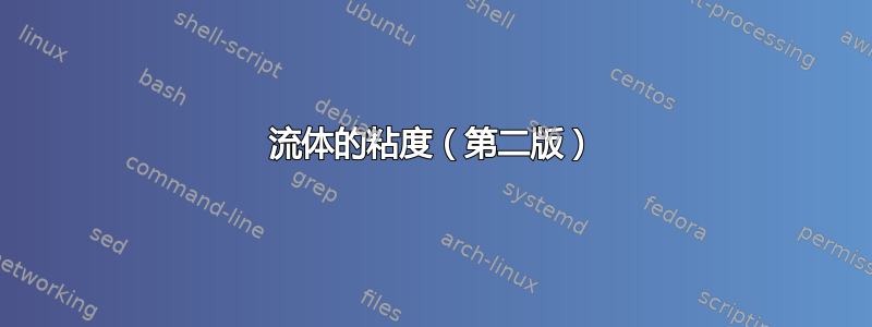
我希望液体的各层(或部分)都是浅蓝色,且厚度较小,并且从左向右流动,而不是相反。我还希望像第一张图那样有标签F(洋红色矢量),A,五(绿色矢量)和高度。如何实现这一点?谢谢。

答案1
每层的厚度由值决定/tikz/3d layer/z。只需将初始值设置为 0.1 即可使层变薄。
我将图层的堆叠转换为一个循环,该循环遍历所有部分,甚至包括第一个和最后一个部分。更改一个图层的外观我可以通过按键来控制。3d layer/layer i
现在将在是= 0 且是= /tikz/3d layer/z。这意味着图层的底部位于图片的指定坐标。图层的顶部将被命名,pic name-top我们可以在下一层中引用它。
(这也是我定义layer-1-top坐标以便图层 0 有引用的原因。)
我已经重新实现了边界框说辞,它的工作原理与我的非常相似节点家族但使用\AtEndDocument钩子(而不是execute at end picture),以便我们
- 只写一个条目
- 但对于当前编译来说,这是最大的
进入 AUX 文件。
代码
% arara: animate: {delay: 20, density: 600, options: ['-alpha', 'remove']}
\documentclass[tikz, border=3mm]{standalone}
\usetikzlibrary{3d, arrows.meta, bending, calc, perspective}
\makeatletter
\tikzset{
  max bounding box/.style={
    execute at end picture={%
      \pgfutil@IfUndefined{tikz@maxbb@#1@prev}{%
        \AtEndDocument{\immediate\write\pgfutil@auxout{%
          \noexpand\expandafter\gdef\noexpand\csname tikz@maxbb@#1@next\endcsname
            {\csname tikz@maxbb@#1@prev\endcsname}}}%
        \tikz@@maxbb@set{#1}%
      }{%
        \expandafter\expandafter\expandafter\tikz@@maxbb@get
          \csname tikz@maxbb@#1@prev\endcsname
        \tikz@@maxbb@set{#1}}%
      \pgfutil@IfUndefined{tikz@maxbb@#1@next}{}{%
        \expandafter\expandafter\expandafter\tikz@@maxbb@get
          \csname tikz@maxbb@#1@next\endcsname}}}}
\def\tikz@@maxbb@get#1#2#3#4{%
  \ifdim#1<\pgf@picminx\global\pgf@picminx#1\fi
  \ifdim#3>\pgf@picmaxx\global\pgf@picmaxx#3\fi
  \ifdim#2<\pgf@picminy\global\pgf@picminy#2\fi
  \ifdim#4>\pgf@picmaxy\global\pgf@picmaxy#4\fi}
\def\tikz@@maxbb@set#1{%
  \expandafter\xdef\csname tikz@maxbb@#1@prev\endcsname
      {{\the\pgf@picminx}{\the\pgf@picminy}{\the\pgf@picmaxx}{\the\pgf@picmaxy}}}%
\makeatother
\tikzset{% https://tex.stackexchange.com/a/688676
  Measure/.tip={>[round, scale=.65, sep=+0pt +.5]},
  dim line distance/.initial=.2cm, dim line all/.code=,
  % instead of the arrow tip Bar, we use a negative shorten
  % so that the arrow still looks acceptable after the transformation
  dim line delim/.style={dim line all, draw, shorten >=+-3\pgflinewidth},
  dim line style/.style={dim line all, -Measure},
  dim line text/.style={midway, auto=false},
  pics/dim line/.style args={#1--#2}{code={
    \path[path only] ($(#1)!\pgfkeysvalueof{/tikz/dim line distance}!90:(#2)$)
      coordinate(dim line@1) -- node[dim line text, style/.expand once=
        \tikzpictextoptions, alias=dim line@text] {\tikzpictext}
      ($(#2)!\pgfkeysvalueof{/tikz/dim line distance}!-90:(#1)$)
      coordinate (dim line@2);
    \draw[dim line delim, line to] (#1) to (dim line@1);
    \draw[dim line delim, line to] (#2) to (dim line@2);
    \path[line to] (dim line@text) edge[dim line style] (dim line@1)
                                   edge[dim line style] (dim line@2);}}}
\tikzset{
  3d layer/.pic={% • no argument, don't need it,
                 %   we can set keys directly in the options of the pic
                 % • define 3×4 + 1 coordinates:
                 %   better would be anchors but that's another topic:
                 %   https://tex.stackexchange.com/a/676090
                 % • z = 0 is at the bottom
      \def\pv##1{\pgfkeysvalueof{/tikz/3d layer/##1}}
      \path[3d layer/all, 3d layer/fore]
          (-\pv{x}/2, -\pv{y}/2,       0) coordinate (-foreBL)
       -- ( \pv{x}/2, -\pv{y}/2,       0) coordinate[alias=-sideBL] (-foreBR)
       -- ( \pv{x}/2, -\pv{y}/2,  \pv{z})
         coordinate[alias=-sideTL, alias=-topBR] (-foreTR)
       -- (-\pv{x}/2, -\pv{y}/2,  \pv{z}) coordinate[alias=-topBL] (-foreTL)
       -- cycle;
      \path[3d layer/all, 3d layer/side] (-sideBL)
       -- ( \pv{x}/2,  \pv{y}/2,       0) coordinate (-sideBR)
       -- ( \pv{x}/2,  \pv{y}/2,  \pv{z}) coordinate[alias=-topTR] (-sideTR)
       -- (-sideTL) -- cycle;
      \path[3d layer/all, 3d layer/top]  (-topBL) -- (-topBR) -- (-topTR)
       -- (-\pv{x}/2,  \pv{y}/2,  \pv{z}) coordinate (-topTL) -- cycle;
      \coordinate (-top) at (0, 0, \pv{z});},
 3d layer/.cd, x/.initial=2, y/.initial=2, z/.initial=0.1,
 fore/.code=, side/.code=, top/.code=, % no ops
 all/.style={draw=blue!80, fill=blue!20},
 top and bottom/.style={
   /tikz/3d layer/layer 0/.append style={3d layer/all/.append style={#1}},
   /tikz/3d layer/layer \totalLayers/.style={3d layer/all/.append style={#1}}}}
\begin{document}
\newcommand*\totalLayers{9}            % i.e. 10
\newcommand*\rightShiftPerPicture{0.005}%
\tikzset{
  3d layer/top and bottom={fill=gray!80},
%  3d layer/top and bottom={fill=blue!60},
  declare function={shiftInPic(\layer,\pic)=%
    (\layer>1 && \layer<\totalLayers)*\rightShiftPerPicture*\pic;},
}
\foreach \picture in {0, ..., 60}{
\begin{tikzpicture}[
  line join=round, line cap=round, >=Latex, arrows={[scale=.75]},
  max bounding box=fluids]
\begin{scope}[3d view={30}{10}] % scope not needed but okay
\coordinate (layer-1-top);
\foreach[count=\prevLayer from -1] \layer in {0, ..., \totalLayers}
  \pic[
    3d layer/layer \layer/.try,
    shift={({shiftInPic(\layer, \picture)}, 0, 0)},
  ] (layer\layer) at (layer\prevLayer-top) {3d layer};

% Apply transformation in the “fore” canvas,
% the value (here 0) doesn't even matter because we always reference a fixed point
\tikzset{canvas is xz plane at y=0, transform shape} % nodes as well
\draw[->, thick, draw=green!75!black]
  (layer9-foreBR) -- +(right:2) node[below left]{$\mathbf v$};
\path % or: \coordinate (@) at ($(…-topBL)!.4!(…-topTL)$); with calc library
  (layer\totalLayers-topBL) -- (layer\totalLayers-topTL) coordinate[pos=.4](@);

\draw[<-, thick, draw=red] (@) -- node[above]{$\mathbf F$} +(left:1);
\node[below right] at (layer0-foreBR) {$\mathbf v = 0$};

\draw[<-] (layer\totalLayers-top) to[bend right] ++ (165:.4)
                                  to[bend  left] ++(165:.4) node[above]{$A$};

\path[] (layer\totalLayers-foreBL) |- coordinate[midway] (@) (layer0-foreTL);
\pic[
  pic text=$L$,
  pic text options={fill opacity=.5, text opacity=1, fill=white,
                    rounded corners=+3pt, inner sep=+.15em, outer sep=+.15em},
] {dim line=@--layer\totalLayers-foreBL};
\end{scope}
\end{tikzpicture}}
\end{document}