

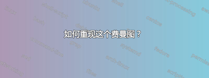
我想重现下图

这是我的代码(我用来tikz绘制一个带有弯曲箭头的循环的椭圆):
\documentclass{article}
\usepackage[compat=1.1.0]{tikz-feynman}
\usetikzlibrary{bending, ext.arrows}
\begin{document}
\begin{tikzpicture}[baseline=(b.base)]
    \begin{feynman}[/tikz/rect/.style={rectangle, draw, minimum size=.1cm, fill=white}]
        \vertex (a);
        \begin{scope}[shift={(3.075,-0.575)}, rotate=-45]
            \draw (0,0) coordinate (center) ellipse (0.775cm and 0.4cm);
            \foreach \sa in {0, 180}
            \foreach \da in {120, -120}
            \path[-{Centered Triangle[scale length=2, bend]}, tips]
            (\sa:1) arc[start angle=\sa, delta angle=\da, x radius=0.775cm, y radius=0.4cm];
            \node[dot, label=90:\(P_{lin}\)] (g) at (0,0.4);
            \node[dot, label=-90:\(P_{lin}\)] (h) at (0,-0.4);
        \end{scope}
        \node[rect, label=90:\(F_3\)] (b) at (2.5, 0);
        \node[dot,label=120:\(P_{lin}\)] (c) at (3.5,1);
        \node[rect, label=-90:\(F_2\)] (d) at (3.65, -1.15);
        \vertex (e) at (4.5,2);
        \vertex (f) at (4.5,-2);
        \diagram*{(b) -- [fermion] (a), (c) -- [fermion] (b), (c) -- [fermion] (e), (d) -- [fermion] (f)};
    \end{feynman}
\end{tikzpicture}}
\end{document}

请注意,箭头没有正确叠加。但是,如果我设置x radius=1cm,箭头会按预期显示,但现在椭圆的尺寸不符合要求。以下是这种情况的代码:
\documentclass{article}
\usepackage[compat=1.1.0]{tikz-feynman}
\usetikzlibrary{bending, ext.arrows}
\begin{document}
\begin{tikzpicture}[baseline=(b.base)]
    \begin{feynman}[/tikz/rect/.style={rectangle, draw, minimum size=.1cm, fill=white}]
        \vertex (a);
        \begin{scope}[shift={(3.075,-0.575)}, rotate=-45]
            \draw (0,0) coordinate (center) ellipse (1cm and 0.4cm);
            \foreach \sa in {0, 180}
            \foreach \da in {120, -120}
            \path[-{Centered Triangle[scale length=2, bend]}, tips]
            (\sa:1) arc[start angle=\sa, delta angle=\da, x radius=1cm, y radius=0.4cm];
            \node[dot, label=90:\(P_{lin}\)] (g) at (0,0.4);
            \node[dot, label=-90:\(P_{lin}\)] (h) at (0,-0.4);
        \end{scope}
        \node[rect, label=90:\(F_3\)] (b) at (2.5, 0);
        \node[dot,label=120:\(P_{lin}\)] (c) at (3.5,1);
        \node[rect, label=-90:\(F_2\)] (d) at (3.65, -1.15);
        \vertex (e) at (4.5,2);
        \vertex (f) at (4.5,-2);
        \diagram*{(b) -- [fermion] (a), (c) -- [fermion] (b), (c) -- [fermion] (e), (d) -- [fermion] (f)};
    \end{feynman}
\end{tikzpicture}}
\end{document}

请帮我解决这个问题。
答案1
您正在使用它(\sa:1)作为圆弧的起点,但您必须对此极坐标使用相同的半径
\draw (0,0) ellipse (0.775 and 0.4);
\foreach \sa in {0, 180}
  \foreach \da in {120, -120}
    \path[-{Centered Triangle[scale length=2, bend]}, tips]
       (\sa:.775 and .4) arc[start angle=\sa, delta angle=\da,
                             x radius=0.775, y radius=0.4];
我还删除了cms,以免混淆坐标和画布坐标系。
代码
\documentclass{article}
\usepackage[compat=1.1.0]{tikz-feynman}
\usetikzlibrary{bending, ext.arrows}
\begin{document}
\begin{tikzpicture}[baseline=(b.base)]
\begin{feynman}[/tikz/rect/.style={rectangle, draw, minimum size=.1cm, fill=white}]
\vertex (a);
\begin{scope}[shift={(3.075,-0.575)}, rotate=-45]
  \draw (0,0) ellipse (0.775 and 0.4);
  \foreach \sa in {0, 180}
    \foreach \da in {120, -120}
      \path[-{Centered Triangle[scale length=2, bend]}, tips]
         (\sa:.775 and .4) arc[start angle=\sa, delta angle=\da,
                               x radius=0.775, y radius=0.4];
  \node[dot, label= 90:\(P_{lin}\)] (g) at (0,0.4);
  \node[dot, label=-90:\(P_{lin}\)] (h) at (0,-0.4);
\end{scope}
\node[rect, label= 90:\(F_3\)] (b) at (2.5, 0);
\node[rect, label=-90:\(F_2\)] (d) at (3.65, -1.15);
\end{feynman}
\end{tikzpicture}
\end{document}
输出

话虽如此,我相信是时候使用一种更自动化的方式来放置箭头了。下面使用一个专门的softpath arrow图片,它使用 PGF 的内部软路径沿曲线(以及直线)部分绘制弯曲的箭头。
而 TikZ-Feynman 已经带来了它的anti majorana关键,即人们再次isosceles triangle沿着路径放置节点而不是箭头提示,这就是anti majorana'关键所在,使用前面提到的图片。
黑点磷lin注释也将通过键沿着边缘放置middle dot,注释是该点上的标签。
顶点之间直接使用曲线路径,而不是椭圆。
这应该是指定这些图表的更自然的方式。
笔记:最好替换 TikZ-Feynman 的一些内部组件,以提供关于三角形、大小、键和所有内容的一致输出,但这需要对源代码进行一些挖掘。
和键middle dot的rect定义与未写明的 TikZ-Feynman 规则手册一致。
代码
\documentclass{article}
\usepackage[compat=1.1.0]{tikz-feynman}
\usetikzlibrary{bending, ext.arrows, quotes}
\makeatletter
\tikzset{
  pos </.initial=0,
  pics/softpath arrow/.style={% does work well for curves and -- lines
    foreground code=, background code=,
    setup code=\pgfsyssoftpath@getcurrentpath\tikz@temp
      \pgfprocesssplitsubpath\tikz@temp\expandafter\pgf@parse@end
      \pgfprocessresultsubpathsuffix\pgf@stop\pgf@stop\pgf@stop,
    code=\pgfset{tips}\pgfsetarrows{#1}\pgftransformreset
      \ifx\pgfpointthirdlastonpath\relax % it's a line
        \pgfpathmoveto{\pgfpointlineattime{\pgfkeysvalueof{/tikz/pos <}}
            {\pgfpointsecondlastonpath}{\pgfpointlastonpath}}%
        \pgfpathlineto{\pgfpointlineattime
          {\tikz@time}{\pgfpointsecondlastonpath}{\pgfpointlastonpath}}%
      \else
        \pgfpathcurvebetweentime{\pgfkeysvalueof{/tikz/pos <}}{\tikz@time}
          {\pgfpointfourthlastonpath}{\pgfpointthirdlastonpath}
          {\pgfpointsecondlastonpath}{\pgfpointlastonpath}%
      \fi
      \pgfusepath{}}}
\makeatother
\tikzfeynmanset{
  Feynman Triangle/.tip={Centered Triangle[scale length=2, bend]},
  middle dot/.style={/tikz/edge node={node[/tikzfeynman/every middle dot@@,#1]{}}},
  every middle dot/.style={/tikzfeynman/every middle dot@@/.append style={#1}},
  every middle dot@@/.style={shape=circle, fill, inner sep=+0pt, minimum size=+5pt},
  rect/.style={/tikzfeynman/every rect@@},
  every rect@@/.style={/tikz/shape=rectangle, /tikz/draw, /pgf/minimum size=.1cm},
  every rect/.style={/tikzfeynman/every rect@@/.append style={#1}},
  anti majorana'/.style args={#1:#2}{
    /tikz/edge node={pic[pos <=#1, pos=#2]{
      softpath arrow=Feynman Triangle-Feynman Triangle}}},
  anti majorana'/.default={.25:.75}}
\begin{document}
\begin{tikzpicture}[baseline=(b.base), bend angle=60, semithick]
\newcommand*\Plin{\(P_{\mathrm{lin}}\)} % that seems to come up more than once
\begin{feynman}
\vertex (a);
\vertex[rect, "\(F_3\)"      ] (b) at (2.5 ,  0   ) {}; % use \vertex … {} here
\vertex[rect, "\(F_2\)" below] (d) at (3.65, -1.15) {}; % use \vertex … {} here
\vertex (e) at (4.5,  2);
\vertex (f) at (4.5, -2);
\diagram*[use existing nodes, /tikz/every label/.append style={inner sep=+.15em}]{
  b -- [fermion] a,
  b -- [middle dot="\Plin" above left, anti majorana'] e,
  d -- [fermion] f,
  b --[bend left, middle dot="\Plin" above right, anti majorana'] d
    --[bend left, middle dot="\Plin" below  left, anti majorana'] b
};
\end{feynman}
\end{tikzpicture}
\end{document}
输出
