

原始问题
我用这个代码画了一辆简单的汽车:
\begin{document}
  \begin{tikzpicture}
    \shade[top color=red, bottom color=white, shading angle={135}]
        [draw=black,fill=red!20,rounded corners=1.2ex,very thick] (1.5,.5) -- ++(0,1) -- ++(1,0.3) --  ++(3,0) -- ++(1,0) -- ++(0,-1.3) -- (1.5,.5) -- cycle;
    \draw[very thick, rounded corners=0.5ex,fill=black!20!blue!20!white,thick]  (2.5,1.8) -- ++(1,0.7) -- ++(1.6,0) -- ++(0.6,-0.7) -- (2.5,1.8);
    \draw[thick]  (4.2,1.8) -- (4.2,2.5);
    \draw[draw=black,fill=gray!50,thick] (2.75,.5) circle (.5);
    \draw[draw=black,fill=gray!50,thick] (5.5,.5) circle (.5);
    \draw[draw=black,fill=gray!80,semithick] (2.75,.5) circle (.4);
    \draw[draw=black,fill=gray!80,semithick] (5.5,.5) circle (.4);

   \shade[top color=red, bottom color=white, shading angle={135}]
   [draw=black,fill=red!20,rounded corners=1.2ex,very thick] (1.5,.5) -- ++(0,1) -- ++(1,0.3) --  ++(3,0) -- ++(1,0) -- ++(0,-1.3) -- (1.5,.5) -- cycle;
   \draw[very thick, rounded corners=0.5ex,fill=black!20!blue!20!white,thick]  (2.5,1.8) -- ++(1,0.7) -- ++(1.6,0) -- ++(0.6,-0.7) -- (2.5,1.8);
   \draw[thick]  (4.2,1.8) -- (4.2,2.5);
   \draw[draw=black,fill=gray!50,thick] (2.75,.5) circle (.5);
   \draw[draw=black,fill=gray!50,thick] (5.5,.5) circle (.5);
   \draw[draw=black,fill=gray!80,semithick] (2.75,.5) circle (.4);
   \draw[draw=black,fill=gray!80,semithick] (5.5,.5) circle (.4);
\end{tikzpicture}
\end{document}
如果我们想让 3 辆车彼此保持一定距离,该怎么办?
根据答案进行编辑
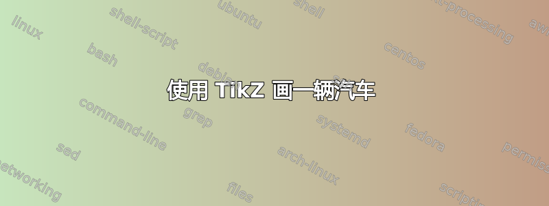
[![在此处输入图片说明][1]][1][![在此处输入图片说明][1]][1]我用这段代码画了一辆简单的汽车:
\documentclass[border=10pt]{standalone}
\usepackage{tikz}

\tikzset{
    pics/my car/.style={
        code={
            \tikzset{my car/.cd, #1}
            \shade[my car/car color, shading angle={135},
                draw=black, rounded corners=1.2ex, very thick]
                (1.5,.5) -- ++(0,1) -- ++(1,0.3) --  ++(3,0) -- ++(1,0)
                    -- ++(0,-1.3) -- (1.5,.5) -- cycle;
            \draw[very thick, rounded corners=0.5ex, fill=black!20!blue!20!white, thick]
                (2.5,1.8) -- ++(1,0.7) -- ++(1.6,0) -- ++(0.6,-0.7) -- (2.5,1.8);
            \draw[thick] (4.2,1.8) -- (4.2,2.5);
            \draw[fill=gray!50, thick]
                (2.75,.5) circle[radius=.5cm]
                (5.5,.5) circle[radius=.5cm];
            \draw[fill=gray!80, semithick]
                (2.75,.5) circle[radius=.4cm]
                (5.5,.5) circle[radius=.4cm];
            \coordinate (-front) at (1.5,1);
            \coordinate (-back) at (6.5,1);
            \coordinate (-top) at (4.25,2.5);
            \coordinate (-bottom) at (4.25,0);
        }
    },
    my car/car color/.style={
        top color=red, bottom color=white
    }
}

\begin{document}
\begin{tikzpicture}

\pic (car 1) at (0,0) {my car};

\pic (car 2) at (10,0) {my car={car color/.append style={top color=blue}}};

\pic (car 3) at (20,0) {my car={car color/.append style={top color=green}}};

\pic (car 4) at (30,0) {my car={car color/.append style={top color=black}}};

%\draw[<-, shorten <=5pt, shorten >=5pt, ultra thick]
  %  (car 1-back) -- (car 2-front);

\draw[line width=5pt][<-, shorten <=5pt, shorten >=5pt]
    (car 1-top) to[out=90, in=90] (car 2-top);
  \draw[line width=5pt][<-, shorten <=5pt, shorten >=5pt]
  (car 2-top) to[out=90, in=90] (car 3-top);
   \draw[line width=5pt][<-, shorten <=5pt, shorten >=5pt]
  (car 3-top) to[out=90, in=90] (car 4-top);

\end{tikzpicture}
\end{document}
答案1
更新:
要添加箭头和其他内容,您可以像添加节点一样添加,显然您必须定义一个特定的点来离开和到达,在本例中,在 Texla 汽车的绘图中,我在顶部添加了一个点,然后就可以使用从一行到另一行的命令以及一行中的节点了。这是一个基本应用程序的示例。
结果:

U-MWE:
\documentclass[tikz,border=3.14mm]{standalone}
\usepackage{tikz}
\usetikzlibrary{calc,arrows.meta}

\begin{document}
    \begin{tikzpicture}[
        >=Triangle
        ]
        %Start drawing the thing...
        % Help lines to plan where put all:
        \def\wcanvas{20}
        \def\hcanvas{6}
        \draw[red!5,step=0.25] (-1,-2) grid (\wcanvas,\hcanvas);
        \draw[cyan!40,step=1,line width=1] (-1,-2) grid (\wcanvas,\hcanvas);
        \foreach \x in {-1, ..., \wcanvas} {%
            \node[anchor=90] at (\x,-2) {\tiny\x};
        }
        \foreach \y in {-2, ..., \hcanvas} {%
            \node[anchor=0] at (-1,\y) {\tiny\y};

        }
        %Creating a weel for all cars
        \def\Weel#1{%\Weel{position}
            \draw[fill=white,shift={(#1)}](0,0)circle (0.3);
            \draw[fill=black!80, even odd rule,shift={(#1)}](0,0) circle (.5) circle (0.3);
            \draw[fill,shift={(#1)}](0,0) circle (0.05);
            \foreach \i in {1,...,12}{\draw[fill,shift={(#1)}](30*\i:0.15)--(30*\i:0.25)--+(90+30*\i:0.05);}
        }

        \def\TexLaCAr#1#2#3#4[#5]{ %\OrigCAr{position}{orientation~restrcited~values~1~or~-1}{rotation}{color}[ID]
            \begin{scope}[shift={(#1)},xscale=#2,rotate=#3]
                \draw(0,0) coordinate (#5) circle (2pt);
                \draw(0.2,1.8) coordinate (#5-top);%<--Added a point on top named nodename-top

                \begin{scope}[x=1pt,y=-1pt,top color=#4,bottom color=black!50,xshift=-90,yshift=57]
                    \shadedraw%Path obtained using Inkscape and tikz path export complement https://github.com/xyz2tex/svg2tikz
                    (7.3, 17.6)
                    -- (96.6, 6.0) -- (153.1, 25.4) -- cycle;
                    \fill
                    (151.9, 24.4)
                    -- (157.7, 27.4) -- (157.2, 41.7) -- (119.9, 45.8) -- (29.2, 46.3)
                    -- (9.8, 39.5) -- (9.3, 35.7) -- (12.8, 35.7) -- (13.8, 20.6)
                    -- cycle;
                    \shadedraw
                    (7.3, 17.1)
                    -- (10.1, 34.2) -- (22.6, 35.5) -- (28.9, 25.1) -- (47.8, 25.1)
                    -- (56.6, 38.2) -- (120.7, 40.0) -- (128.5, 26.9) -- (146.9, 26.9)
                    -- (153.1, 36.7) -- (157.2, 36.7) -- (157.6, 27.6) -- (152.9, 26.8)
                    -- (152.9, 25.1) -- cycle;
                    \fill
                    (137.2, 22.0)
                    -- (96.2, 7.7) -- (63.5, 11.2) -- (62.9, 17.0) -- cycle;
                    \draw
                    (62.7, 17.2) -- (62.4, 20.4) -- (63.2, 38.7) -- (64.1, 45.6);
                    \draw
                    (90.9, 19.2) -- (91.4, 23.1) -- (92.7, 45.5);
                    \draw
                    (120.6, 21.2) -- (121.5, 24.0) -- (120.8, 45.4);
                \end{scope}
                \Weel{1.67,0.5}
                \Weel{-1.8,0.5}
                \ifnum#2=-1{\draw(0,0)++(0,2.5em)node[rotate=-#3]{\TeX \raisebox{-0.49ex}{L}A};}\fi
                \ifnum#2=1{\draw(0,0)++(0,2.5em)node[rotate=#3]{\TeX \raisebox{-0.49ex}{L}A};}\fi
            \end{scope}
        }

        % drawing the Cars
        \TexLaCAr{3,0}{1}{0}{white}[CAR-1]
        \TexLaCAr{$(CAR-1)+(6,0)$}{1}{0}{white!50!red}[CAR-2]
        \TexLaCAr{$(CAR-2)+(7,0)$}{1}{0}{white!50!blue!}[CAR-3]

        %using ARCS
        \draw[->](CAR-1-top) arc (180:0:2.9)node[pos=0.5, anchor=-90]{$t_1$};
        \draw[->](CAR-2-top) arc (180:0:3.4)node[pos=0.5, anchor=-90]{$t_2$};
        %Using controls
        \draw[->,red,dashed](CAR-1-top) .. controls ++(60:3) and ++(120:3) .. (CAR-2-top)node[pos=0.5, anchor=-90]{$t_1$};
        \draw[->,red,dashed](CAR-2-top) .. controls ++(60:3) and ++(120:3) ..(CAR-3-top)node[pos=0.5, anchor=-90]{$t_2$};
        \draw[->,blue,dashed,thick](CAR-1-top) .. controls ++(80:4) and ++(100:4) ..($(CAR-3-top)+(0.1,0)$)node[pos=0.5, anchor=-90]{$t_1+t_2$};
        %Draing some distances
        \draw[|<->|,dashdotted,green!50!black, thick] (CAR-1)++(0,-0.3) -- ($(CAR-2)+(0,-0.3)$) node[midway,below]{6 su};
        \draw[|<->|,dashdotted,green!50!black, thick] (CAR-2)++(0,-0.3) -- ($(CAR-3)+(0,-0.3)$) node[midway,below]{7 su};
        \draw[|<->|,dashdotted,green!50!black, thick] (CAR-1)++(0,-0.9) -- ($(CAR-3)+(0,-0.9)$) node[midway,below]{7 su + 6 su = 13 su};

    \end{tikzpicture}
\end{document}
原来的:
只是为了好玩,并将我的例子改编到你的情况,并指出一些重要的事情,第一件事是你应该尝试根据绘图中心的锚点进行绘制,这样你就可以利用镜像来改变方向; 您还可以定义某些点并为所有情况分配一个 ID; 我将该点保留为每个绘图0.0的坐标,以便以后使用,也是汽车前部的点,以防您想在它们之间制作一个尺寸。
仅通过查看代码来绘制具有复杂形状的东西可能会非常复杂,有很多方法可以绘制像车辆这样复杂的东西,您只需求助于其他免费工具,例如 Inkscape,您可以选择打开 SVG 文件并将其保存为 PDF 格式,然后使用 include 图形将其导入到节点中的绘图中,缩放它并添加点或文本;但是,您将无法更改颜色;为此,您可以做的是跟踪路径,尽量使它们保持最小,然后使用扩展程序将这些笔触导出到 tikz。
您依次获得的笔触必须适应您的绘图大小,幸运的是,您可以使用范围缩放和移动所有点,然后将它们嵌套在定义中,剩下的就是修复问题,修复代码以便可以读取,等等。最终,您会得到一个框架,您可以像使用贴纸一样使用它们。
结果:

梅威瑟:
\documentclass[tikz,border=3.14mm]{standalone}
\usepackage{tikz}
\usetikzlibrary{calc,math}

\begin{document}
    \begin{tikzpicture}
        %Start drawing the thing...
        % Help lines to plan where put all:
        \def\wcanvas{15}
        \def\hcanvas{12}
        \draw[red!5,step=0.25] (-1,-1) grid (\wcanvas,\hcanvas);
        \draw[cyan!40,step=1,line width=1] (-1,-1) grid (\wcanvas,\hcanvas);
        \foreach \x in {-1, ..., \wcanvas} {%
            \node[anchor=90] at (\x,-1) {\tiny\x};
        }
        \foreach \y in {-1, ..., \hcanvas} {%
            \node[anchor=0] at (-1,\y) {\tiny\y};

        }
        %Creating a weel for all cars
        \def\Weel#1{%\Weel{position}
            \draw[fill=white,shift={(#1)}](0,0)circle (0.3);
            \draw[fill=black!80, even odd rule,shift={(#1)}](0,0) circle (.5) circle (0.3);
            \draw[fill,shift={(#1)}](0,0) circle (0.05);
            \foreach \i in {1,...,12}{\draw[fill,shift={(#1)}](30*\i:0.15)--(30*\i:0.25)--+(90+30*\i:0.05);}
        }
        %Creating a Macro to draw the original car
        \def\OrigCAr#1#2#3#4[#5]{ %\OrigCAr{position}{orientation~restrcited~values~1~or~-1}{rotation}{color}[ID]
            \begin{scope}[shift={(#1)},xscale=#2,rotate=#3]
                \draw(0,0) coordinate (#5) circle (2pt);
                \shadedraw[
                top color=#4,
                bottom color=white,
                shading angle={135},
                draw=black,
                fill=red!20,
                rounded corners=1.2ex,
                very thick,
                xshift=-40mm,%To center your draw to the anchor point at 0,0 to use as drawing block
                ]
                (1.5,.5)
                -- ++(0,1)
                -- ++(1,0.3)
                -- ++(3,0)
                -- ++(1,0)
                -- ++(0,-1.3)
                -- (1.5,.5) coordinate (#5-front) % You can define some points in the shape to use later
                -- cycle;
                \draw[very thick, rounded corners=0.5ex,fill=black!20!blue!20!white,thick,xshift=-40mm]
                (2.5,1.8)
                -- ++(1,0.7)
                -- ++(1.6,0)
                -- ++(0.6,-0.7)
                -- (2.5,1.8);
                \draw[thick,xshift=-40mm,]  (4.2,1.8) -- (4.2,2.5);
                %\draw[draw=black,fill=gray!50,thick] (2.75,.5) circle (.5);
                \Weel{$(2.75,.5)+(-40mm,0)$}
                %\draw[draw=black,fill=gray!50,thick] (5.5,.5) circle (.5);
                \Weel{$(5.5,.5)+(-40mm,0)$}
                \ifnum#2=-1{\draw(0,0)++(0,2.5em)node[rotate=-#3]{#5};}\fi
                \ifnum#2=1{\draw(0,0)++(0,2.5em)node[rotate=#3]{#5};}\fi
            \end{scope}
        }

        \def\SuvCAr#1#2#3#4[#5]{ %\OrigCAr{position}{orientation~restrcited~values~1~or~-1}{rotation}{color}[ID]
            \begin{scope}[shift={(#1)},xscale=#2,rotate=#3]
                \def\CarLenght{5}
                \fill[black!50!#4](-\CarLenght/2.5,0.5) rectangle ++(\CarLenght*0.86,8mm);
                \Weel{\CarLenght*1.9/6,0.5}
                \Weel{-\CarLenght*1.45/6,0.5}
                \draw(0,0) coordinate (#5) circle (2pt);
                \begin{scope}[%this way to put optios allows you to add comments for each also enable or disble them
                    top color=#4,
                    bottom color=white,
                    shading angle={135+#3},
                    %opacity=0.5,%some dissabled option
                    x=1pt,%Must be the same as the unit value in tikz path export option
                    y=-1pt,%idem
                    scale=0.31,%To size all to the scale of the original car
                    xshift=-230,%To put all in the planned anchor for definition
                    yshift=220%idem
                    ]
                    \shadedraw
                    (69.0, 179.9)%Path obtained using Inkscape and tikz path export complement https://github.com/xyz2tex/svg2tikz
                    .. controls (69.0, 179.9) and (65.4, 116.6) .. (118.8, 116.6)
                    .. controls (172.1, 116.6) and (171.4, 180.7) .. (171.4, 180.7)
                    -- (326.5, 179.2)
                    .. controls (326.5, 179.2) and (318.6, 115.9) .. (374.8, 115.9)
                    .. controls (431.0, 115.9) and (427.5, 180.7) .. (427.5, 180.7)
                    .. controls (427.5, 180.7) and (445.9, 182.8) .. (453.1, 175.7)
                    .. controls (460.2, 168.6) and (460.9, 135.8) .. (458.7, 133.0)
                    .. controls (456.6, 130.2) and (446.7, 118.8) .. (446.7, 118.8)
                    .. controls (446.7, 118.8) and (449.5, 98.2) .. (440.3, 91.0)
                    .. controls (431.0, 83.9) and (356.3, 80.4) .. (346.4, 74.0)
                    .. controls (336.4, 67.6) and (285.9, 23.5) .. (268.8, 15.6)
                    .. controls (251.8, 7.8) and (83.2, 8.5) .. (71.1, 14.2)
                    .. controls (59.0, 19.9) and (40.5, 69.7) .. (40.5, 69.7)
                    .. controls (40.5, 69.7) and (44.8, 46.9) .. (26.3, 46.2)
                    .. controls (7.8, 45.5) and (6.4, 56.2) .. (5.0, 83.9)% circle (3pt) %uncoment to see where is in the draw
                    .. controls (3.6, 111.7) and (4.3, 126.6) .. (14.9, 127.3)
                    .. controls (25.6, 128.0) and (32.0, 127.3) .. (32.0, 127.3)
                    .. controls (32.0, 127.3) and (21.3, 147.9) .. (30.6, 165.0)
                    .. controls (39.8, 182.1) and (69.0, 179.9) .. (69.0, 179.9)
                    -- cycle;

                    \draw[fill=#4!80!white,rounded corners]
                    (168.6, 86.1)
                        -- (170.0, 22.0) -- (75.4, 22.8) -- (54.1, 88.2)
                        -- cycle;
                    \draw[fill=#4!80!white,rounded corners]
                    (188.5, 22.8)
                        -- (187.8, 87.5) -- (328.6, 86.8) -- (262.4, 22.8)
                        -- cycle;
                \end{scope}
                \ifnum#2=-1{\draw(0,0)++(0,2.5em)node[rotate=-#3]{#5};}\fi
                \ifnum#2=1{\draw(0,0)++(0,2.5em)node[rotate=#3]{#5};}\fi
            \end{scope}
        }

        \def\TexLaCAr#1#2#3#4[#5]{ %\OrigCAr{position}{orientation~restrcited~values~1~or~-1}{rotation}{color}[ID]
            \begin{scope}[shift={(#1)},xscale=#2,rotate=#3]
                \draw(0,0) coordinate (#5) circle (2pt);

                \begin{scope}[x=1pt,y=-1pt,top color=#4,bottom color=black!50,xshift=-90,yshift=57]
                    \shadedraw%Path obtained using Inkscape and tikz path export complement https://github.com/xyz2tex/svg2tikz
                    (7.3, 17.6)
                        -- (96.6, 6.0) -- (153.1, 25.4) -- cycle;
                    \fill
                    (151.9, 24.4)
                        -- (157.7, 27.4) -- (157.2, 41.7) -- (119.9, 45.8) -- (29.2, 46.3)
                        -- (9.8, 39.5) -- (9.3, 35.7) -- (12.8, 35.7) -- (13.8, 20.6)
                        -- cycle;
                    \shadedraw
                    (7.3, 17.1)
                        -- (10.1, 34.2) -- (22.6, 35.5) -- (28.9, 25.1) -- (47.8, 25.1)
                        -- (56.6, 38.2) -- (120.7, 40.0) -- (128.5, 26.9) -- (146.9, 26.9)
                        -- (153.1, 36.7) -- (157.2, 36.7) -- (157.6, 27.6) -- (152.9, 26.8)
                        -- (152.9, 25.1) -- cycle;
                    \fill
                    (137.2, 22.0)
                        -- (96.2, 7.7) -- (63.5, 11.2) -- (62.9, 17.0) -- cycle;
                    \draw
                    (62.7, 17.2) -- (62.4, 20.4) -- (63.2, 38.7) -- (64.1, 45.6);
                    \draw
                    (90.9, 19.2) -- (91.4, 23.1) -- (92.7, 45.5);
                    \draw
                    (120.6, 21.2) -- (121.5, 24.0) -- (120.8, 45.4);
                \end{scope}
                \Weel{1.67,0.5}
                \Weel{-1.8,0.5}
                \ifnum#2=-1{\draw(0,0)++(0,2.5em)node[rotate=-#3]{\TeX \raisebox{-0.49ex}{L}A};}\fi
                \ifnum#2=1{\draw(0,0)++(0,2.5em)node[rotate=#3]{\TeX \raisebox{-0.49ex}{L}A};}\fi


            \end{scope}
        }

        % drawing the Cars
        \OrigCAr{3,9}{-1}{0}{green}[CAR-1]
        \OrigCAr{$(CAR-1)+(7,0)$}{1}{0}{cyan}[CAR-2]
        \SuvCAr{$(CAR-2)+(0,-5)$}{1}{0}{black}[CAR-3]
        \SuvCAr{$(CAR-1)+(0,-2)$}{-1}{135}{red!50!black}[CAR-4]
        \TexLaCAr{3,0}{1}{0}{white}[CAR-5]
        \TexLaCAr{$(CAR-5)+(7,1)$}{-1}{-15}{green!30!black}[CAR-6]

        %Draing some distances: Valid only for vertical or horizontal dimensions
        \def\AcotX[#1][#2]#3#4{ %\AcotX[nodename_A][nodemame_b]{_known distance}{color}
            \draw[|<->|,draw=#4] (#1)++(0,-0.3) -- ($(#2)+(0,-0.3)$) node[midway,below]{#3 su};
        }
        \def\AcotY[#1][#2]#3#4{ %\AcotX[nodename_A][nodemame_b]{_known distance}{color}
            \draw[|<->|,draw=#4] (#1)++(-0.3,0) -- ($(#2)+(-0.3,0)$) node[midway,left]{#3 su};
        }

        \AcotX[CAR-1][CAR-2]{7}{blue}
        \AcotX[CAR-1-front][CAR-2-front]{2?}{blue}
        \AcotY[CAR-1][CAR-4]{2}{red}

    \end{tikzpicture}
\end{document}
答案2
定义了一个命令\mzncar。它需要 2 个参数。第一个参数是用于移动汽车的坐标。此参数是可选的,具有默认值(0,0)。第二个参数是颜色。
\documentclass[border=6pt]{standalone}
\usepackage{tikz}
\newcommand{\mzncar}[2][(0,0)]{
\begin{scope}[shift={#1}]
\shade[top color=#2, bottom color=white, shading angle=135, draw=black, rounded corners=1.2ex, very thick] (1.5,.5) -- ++(0,1) -- ++(1,0.3) -- ++(3,0) -- ++(1,0) -- ++(0,-1.3) -- (1.5,.5) -- cycle;
\draw[very thick, rounded corners=0.5ex, fill=black!20!blue!20!white, thick] (2.5,1.8) -- ++(1,0.7) -- ++(1.6,0) -- ++(0.6,-0.7) -- (2.5,1.8);
\draw[thick] (4.2,1.8) -- (4.2,2.5);
\draw[fill=gray!50,thick] (2.75,.5) circle[radius=.5];
\draw[fill=gray!50,thick] (5.5,.5) circle[radius=.5];
\draw[fill=gray!80,semithick] (2.75,.5) circle[radius=.4];
\draw[fill=gray!80,semithick] (5.5,.5) circle[radius=.4];
\end{scope}
}
\begin{document}
\begin{tikzpicture}
\mzncar{red}
\mzncar[(6,0)]{green}
\mzncar[(3,-3)]{blue}
\end{tikzpicture}
\end{document}

答案3
您可以随时创建\pic基于部分代码的版本,以便轻松重用它:
\documentclass[border=10pt]{standalone}
\usepackage{tikz}

\tikzset{
    pics/my car/.style={
        code={
            \tikzset{my car/.cd, #1}
            \shade[my car/car color, shading angle={135},
                draw=black, rounded corners=1.2ex, very thick]
                (1.5,.5) -- ++(0,1) -- ++(1,0.3) --  ++(3,0) -- ++(1,0)
                    -- ++(0,-1.3) -- (1.5,.5) -- cycle;
            \draw[very thick, rounded corners=0.5ex, fill=black!20!blue!20!white, thick]
                (2.5,1.8) -- ++(1,0.7) -- ++(1.6,0) -- ++(0.6,-0.7) -- (2.5,1.8);
            \draw[thick] (4.2,1.8) -- (4.2,2.5);
            \draw[fill=gray!50, thick]
                (2.75,.5) circle[radius=.5cm]
                (5.5,.5) circle[radius=.5cm];
            \draw[fill=gray!80, semithick]
                (2.75,.5) circle[radius=.4cm]
                (5.5,.5) circle[radius=.4cm];
        }
    },
    my car/car color/.style={
        top color=red, bottom color=white
    }
}

\begin{document}
\begin{tikzpicture}

\pic {my car};

\pic at (0,-3) {my car={car color/.append style={top color=blue}}};

\pic[xscale=-1] at (14,-1.5)
    {my car={car color/.append style={top color=green!50!black}}};

\end{tikzpicture}
\end{document}

您还可以在您的中放置坐标\pic并使用这些坐标连接不同的\pics:
\documentclass[border=10pt]{standalone}
\usepackage{tikz}

\tikzset{
    pics/my car/.style={
        code={
            \tikzset{my car/.cd, #1}
            \shade[my car/car color, shading angle={135},
                draw=black, rounded corners=1.2ex, very thick]
                (1.5,.5) -- ++(0,1) -- ++(1,0.3) --  ++(3,0) -- ++(1,0)
                    -- ++(0,-1.3) -- (1.5,.5) -- cycle;
            \draw[very thick, rounded corners=0.5ex, fill=black!20!blue!20!white, thick]
                (2.5,1.8) -- ++(1,0.7) -- ++(1.6,0) -- ++(0.6,-0.7) -- (2.5,1.8);
            \draw[thick] (4.2,1.8) -- (4.2,2.5);
            \draw[fill=gray!50, thick]
                (2.75,.5) circle[radius=.5cm]
                (5.5,.5) circle[radius=.5cm];
            \draw[fill=gray!80, semithick]
                (2.75,.5) circle[radius=.4cm]
                (5.5,.5) circle[radius=.4cm];
            \coordinate (-front) at (1.5,1);
            \coordinate (-back) at (6.5,1);
            \coordinate (-top) at (4.25,2.5);
            \coordinate (-bottom) at (4.25,0);
        }
    },
    my car/car color/.style={
        top color=red, bottom color=white
    }
}

\begin{document}
\begin{tikzpicture}

\pic (car 1) at (0,0) {my car};

\pic (car 2) at (10,0) {my car={car color/.append style={top color=blue}}};

\draw[<-, shorten <=5pt, shorten >=5pt, ultra thick]
    (car 1-back) -- (car 2-front);

\draw[<-, shorten <=5pt, shorten >=5pt, ultra thick]
    (car 1-top) to[out=90, in=90] (car 2-top);

\end{tikzpicture}
\end{document}
