

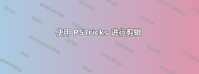
考虑以下示例。
代码
\documentclass{article}

\usepackage{pstricks-add}

\begin{document}

\begin{figure}
\psset{unit=0.05}
 \begin{pspicture}(120,216)
  \pnodes{P}(0,0)(0,120)(186,120)(216,120)(216,0)(186,0)(186,30)(186,90)
  \pspolygon(P0)(P1)(P3)(P4)
  \pcline[offset=12pt]{|<->|}(P1)(P3)
  \ncput*[nrot=:U]{216}
  \pcline[offset=12pt]{|<->|}(P3)(P4)
  \ncput*[nrot=:U]{120}
  \pspolygon[linestyle=none,fillstyle=vlines](P2)(P3)(P4)(P5)
  \pswedge[linestyle=none,fillstyle=solid,fillcolor=white](P6){30}{270}{90}
  \pswedge[linestyle=none,fillstyle=solid,fillcolor=white](P7){30}{270}{90}
  \psarc(P6){30}{270}{90}
  \psarc(P7){30}{270}{90}
  \psdot(P6)
  \psdot(P7)
 \end{pspicture}
\end{figure}

\end{document}
输出

问题
上面的代码似乎是创建图形的错误方法。我猜\pscustom是可行的方法,但我不知道如何使用它;如何使用 PSTricks 以“最佳”方式生成图形?(我非常想看看它是如何完成的,而不仅仅是得到关于使用这个或那个的评论。)
答案1
两个框架和两个圆弧或\pscustom:
\documentclass{article}
\usepackage{pstricks-add}
\begin{document}

\psset{unit=1pt}
\begin{pspicture}(240,140)
\psframe[dimen=middle](216,120)
\psframe[fillstyle=vlines,linestyle=none](186,0)(216,120)
\psarc[fillstyle=solid,fillcolor=white](186,30){30}{-90}{90}
\psarc[fillstyle=solid,fillcolor=white](186,90){30}{-90}{90}
\psdots(186,30)(186,90)
\pcline[offset=12pt]{|<->|}(0,120)(216,120) \ncput*{216}
\pcline[offset=12pt]{|<->|}(216,120)(216,0) \ncput*[nrot=:U]{120}
\end{pspicture}

\begin{pspicture}(240,140)
\psframe[dimen=middle](216,120)
\pscustom[fillstyle=vlines,hatchcolor=red]{%
  \psarc(186,30){30}{-90}{90}
  \psarc(186,90){30}{-90}{90}
  \psline(186,120)(216,120)(216,0)
}
\psdots(186,30)(186,90)
\pcline[offset=12pt]{|<->|}(0,120)(216,120) \ncput*{216}
\pcline[offset=12pt]{|<->|}(216,120)(216,0) \ncput*[nrot=:U]{120}
\end{pspicture}

\end{document}

由于\psframe绘制了一条封闭路径(正确剪切所需),\pscustom如果使用剪切功能,它也可以作为最后的组件添加:
\documentclass{article}
\usepackage{pstricks-add}% http://tug.org/PSTricks/main.cgi/
\begin{document}

\begin{figure}
\psset{unit=1pt}
\begin{pspicture}(240,140)
\psclip{\psset{linestyle=solid}
  \pscustom{
    \psarc(186,30){30}{-90}{90}
    \psarc(186,90){30}{-90}{90}
    \psframe[dimen=middle](216,120)
  }
}
  \psframe[fillstyle=vlines,linestyle=none](186,0)(216,120)
\endpsclip
\psdots(186,30)(186,90)
\pcline[offset=12pt]{|<->|}(0,120)(216,120) \ncput*{216}% Top dimension
\pcline[offset=12pt]{|<->|}(216,120)(216,0) \ncput*[nrot=:U]{120}% Right dimension
\end{pspicture}
\end{figure}

\end{document}
这也是可行的,因为它的结构和\psframe绘制方式(从中间向左逆时针)。
答案2
我正在尝试改进现有的答案。
- 箭头说明符
|<->|应更改为,|<*->|*以使|类似尖端正确对齐。 - 最好是全局传递
dimen=middle给\pscustom而不是本地指定给默认情况下的每个命令dimen=outer。 由于裁剪区域是在描摹裁剪路径后再绘制的,所以一般情况下,裁剪后需要再次描摹裁剪路径。
如果你想明白我的意思,我已经在 Werner 的编辑中添加了
hatchcolor=red,hatchsep=1pt剪辑\psframe。最初 Werner 的设置是hatchcolor=black这样的,所以它是不可察觉的,但现在随着颜色的变化,“缺陷”在视觉上显而易见,如下所示。
这就是为什么剪辑之后需要重新描边的原因。
unit=1pt应避免使用,因为导航网格会变得混乱。

\documentclass[pstricks,border=12pt]{standalone}
\usepackage{pst-node}
\def\Path[#1]{%
  \pscustom[dimen=middle,#1]{
    \psarc(186,30){30}{-90}{90}
    \psarc(186,90){30}{-90}{90}
    \psframe(216,120)
  }\ignorespaces
}

\begin{document}

\psset{unit=1pt,linewidth=3pt}
\begin{pspicture}(240,140)
\psclip{\Path[linestyle=none]}
  \psframe[fillstyle=vlines,hatchcolor=red,hatchsep=1pt,linestyle=none](186,0)(216,120)
\endpsclip
\Path[]
\psdots(186,30)(186,90)
\pcline[offset=12pt]{|<*->|*}(0,120)(216,120) \ncput*{216}% Top dimension
\pcline[offset=12pt]{|<*->|*}(216,120)(216,0) \ncput*[nrot=:U]{120}% Right dimension
\end{pspicture}

\end{document}