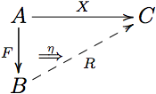
在 xy 的 2cell 包中,有一个用于在复合箭头之间排版 2cells 的命令,即\..compositearrow(其中 .. 代表 u,l,d,r 的某个数字)。
我想使用此命令复制定义图菅延:

除了我希望双箭头 $\eta$ two 从节点 $B$ 指向箭头 $X$ 的中间(毕竟,这是从 $RF$ 到 $X$ 的自然变换)。该\..compositearrow命令似乎是为此目的量身定制的,只是我不知道如何在复合箭头中标记中间源/目标对象。
使用标记
\diagram
A\drcompositemap<4>_{a}^{b}{c}\drlowertwocell{\omit} &\\
& C\\
\enddiagram
我得到:

我如何标记箭头 $a$ 的目标对象和箭头 $b$ 的源对象?
另请参阅我的问题将 2cell 选项中的 xtwocell 箭头方向改为 xy另一种尝试方法见此图
答案1
我会再次使用tikz-cd这里。
这种short风格可以帮助我们绘制直的仅在完整路径的一段上绘制线。(对于曲线来说,这并不容易!)
如果节点没有以矩阵的方式排列,则可以根据需要使用普通的 TikZ 图片(参见第二个示例)。
代码
\documentclass[tikz,convert=false]{standalone}
\usepackage{tikz-cd}
\usetikzlibrary{positioning}
\newcommand*{\tikzcdset}{\pgfqkeys{/tikz/commutative diagrams}}
\tikzset{tikzcd/.code=\tikzcdset{#1}}
\tikzcdset{
  to node/.style={%
    /tikz/execute at begin to=\edef\tikztotarget{#1}}}
\makeatletter
\tikzcdset{
  short shift >/.initial=+.6em,
  short shift </.initial=+.6em,
  short center/.initial=.55,
  short/.style={
    to path={
      \pgfextra
        \pgfinterruptpath
          \path (\tikztostart) coordinate (@aux1) -- (\tikztotarget) coordinate (@aux2);
        \endpgfinterruptpath
        \pgfpointdiff{\pgfpointanchor{@aux1}{center}}{\pgfpointanchor{@aux2}{center}}%
        \pgfmathveclen@{\pgfmath@tonumber{\pgf@x}}{\pgfmath@tonumber{\pgf@y}}%
        \edef\pgfpathlength{\pgfmathresult pt}%
        \pgfcoordinate
          {@@aux1}
          {\pgfpointlineatdistance
            {(\pgfkeysvalueof{/tikz/commutative diagrams/short center})*\pgfpathlength-\pgfkeysvalueof{/tikz/commutative diagrams/short shift <}}
            {\pgfpointanchor{@aux1}{center}}
            {\pgfpointanchor{@aux2}{center}}}%
        \pgfcoordinate
          {@@aux2}
          {\pgfpointlineatdistance
            {(\pgfkeysvalueof{/tikz/commutative diagrams/short center})*\pgfpathlength+\pgfkeysvalueof{/tikz/commutative diagrams/short shift >}}
            {\pgfpointanchor{@aux1}{center}}
            {\pgfpointanchor{@aux2}{center}}}%
      \endpgfextra
        (@@aux1) -- (@@aux2) \tikztonodes}}
}
\tikzset{% from CVS version
  edge node/.code={\expandafter\def\expandafter\tikz@tonodes\expandafter{\tikz@tonodes #1}},
  edge label/.style={/tikz/edge node={node[auto]{#1}}},
  edge label'/.style={/tikz/edge node={node[auto,swap]{#1}}},
  mlabel/.style={/tikz/edge node={node[auto]{$#1$}}},
  mlabel'/.style={/tikz/edge node={node[auto,swap]{$#1$}}}
}
\makeatother
\begin{document}
\begin{tikzcd}
A \rar{a}
  \drar[out=-90, in=180][coordinate,name=ac]{}
  & B \dar{b}
      \dar[short, Rightarrow, to node=ac]{c} \\ % doesn't matter what \*ar is used
  & C
\end{tikzcd}
\begin{tikzpicture}[tikzcd=every diagram, node distance=.5cm and 1cm]
\node                          (B) {$B$};
\node at ([shift=(170:1.5)] B) (A) {$A$};
\node at ([shift=(-80:1.5)] B) (C) {$C$};

\path[tikzcd={every arrow, every label}] (A) edge[mlabel=a] (B)
                                             edge[out=-90, in=180] coordinate (ac) (C)
                                         (B) edge[mlabel=b] (C)
                                             edge[tikzcd={short, Rightarrow}, mlabel=c] (ac);
\end{tikzpicture}
\end{document}
输出


