

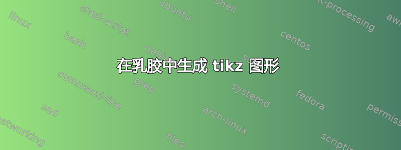
我正在尝试生成tikz类似如下的图形

到目前为止我制作了以下乳胶代码:
\documentclass{article}
\usepackage[utf8]{inputenc}
\usepackage{amsmath}
\usepackage{booktabs}
\usepackage{caption}
\usepackage{tikz}
\usetikzlibrary{positioning}

\tikzset{
  pics/BitArray/.style n args={2}{
  code={\begin{scope}[#2]
  \fill
    \foreach \row [count=\y] in {#1} {
      \foreach \cell [count=\x] in \row {
        \ifnum\cell=1 %
          (\x-1, -\y+1) rectangle ++(1, -1)
        \fi
        \pgfextra{%
          \global\let\maxx\x
          \global\let\maxy\y
        }%
      }
    }
  ;
  \draw[thin] (0, 0) grid[step=1] (\maxx, -\maxy);
  \end{scope}
  }
 }
}


\begin{document}
\[
\begin{tikzpicture}[scale=5]
[baseline=(N.base)]
\begin{scope}[local bounding box=BA1,scale=0.4]
 \foreach \y in {0.2,0.4,...,1.8} {
      \foreach \x in {0.2,0.4,...,1.2} {
          \pgfmathparse{0.9*rnd+0.01}
          \definecolor{MyColor}{rgb}{\pgfmathresult,\pgfmathresult,\pgfmathresult}
          \node[fill=MyColor,inner sep=0.4cm,outer sep=0pt,anchor=center] at (\x,\y) {};
      }
  }
  \draw[step=.2,help lines] (0,0) grid (1.4,2);

\end{scope}
\node[above=1pt of BA1] {$D$};
\node[left=1pt of BA1.north west] {$X$};
\node[left=1pt of BA1.west] (N) {$N$};
\end{tikzpicture}
~\sim~
\begin{tikzpicture}[baseline=(N2.base)]
\begin{scope}[local bounding box=BA2,scale=0.5]
 \pic[right=3cm of BA1.north east] {BitArray={%
    {1,1,1,1},
    {1,1,1,0},
    {1,0,1,1},
    {1,0,0,1},
    {1,1,0,0},
    {0,1,0,1},
    {0,0,1,0},
    {0,1,0,0},
    {0,0,0,0},
    {0,0,0,0}%
  }{fill=black,scale=0.5}};
\end{scope}
\node[left=1pt of BA2.north west] {$\mathbf{Z}$};
\node[above=1pt of BA2] {$K$};
\node[left=1pt of BA2.west] (N2) {$N$};
\end{tikzpicture}
~\dots~*
\begin{tikzpicture}[scale=5][baseline=(dots.base)]
\begin{scope}[local bounding box=BA3,scale=0.4]
 \foreach \y in {0.2,0.4,...,0.6} {
      \foreach \x in {0.2,0.4,...,1.2} {
          \pgfmathparse{0.9*rnd+0.01}
          \definecolor{MyColor}{rgb}{\pgfmathresult,\pgfmathresult,\pgfmathresult}
          \node[fill=MyColor,inner sep=0.4cm,outer sep=0pt,anchor=center] at (\x,\y) {};
      }
  }
  \draw[step=.2,help lines] (0,0) grid (1.4,0.8);

\end{scope}
\node[below=1pt of BA3.south] (dots) {$\vdots$};
\end{tikzpicture}
\]
\end{document}
关于如何完成我的身材有什么建议吗?
第二个问题:例如,我怎样才能gamma distribution使用tikz?可能吗?
答案1
这是一份提案。您的baselines 是正确的 除了你把它们放在单独的[...]括号中。除此之外,你可能还想加载decorations.pathreplacing括号的库等等。(我不得不将一些节点移到左边,因为否则它们会干扰括号。)
\documentclass{article}
\usepackage[utf8]{inputenc}
\usepackage{amsmath}
\usepackage{booktabs}
\usepackage{caption}
\usepackage{tikz}
\usetikzlibrary{positioning,decorations.pathreplacing}

\tikzset{
  pics/BitArray/.style n args={2}{
  code={\begin{scope}[#2]
  \fill
    \foreach \row [count=\y] in {#1} {
      \foreach \cell [count=\x] in \row {
        \ifnum\cell=1 %
          (\x-1, -\y+1) rectangle ++(1, -1)
        \fi
        \pgfextra{%
          \global\let\maxx\x
          \global\let\maxy\y
        }%
      }
    }
  ;
  \draw[thin] (0, 0) grid[step=1] (\maxx, -\maxy);
  \end{scope}
  }
 }
}


\begin{document}
\[
\begin{tikzpicture}[scale=5,baseline=(N.base)]
\begin{scope}[local bounding box=BA1,scale=0.4]
 \foreach \y in {0.2,0.4,...,1.8} {
      \foreach \x in {0.2,0.4,...,1.2} {
          \pgfmathparse{0.9*rnd+0.01}
          \definecolor{MyColor}{rgb}{\pgfmathresult,\pgfmathresult,\pgfmathresult}
          \node[fill=MyColor,inner sep=0.4cm,outer sep=0pt,anchor=center] at (\x,\y) {};
      }
  }
  \draw[step=.2,help lines] (0,0) grid (1.4,2);

\end{scope}
\node[above=1pt of BA1] {$D$};
\node[left=10pt of BA1.north west] {$X$};
\node[left=10pt of BA1.west] (N) {$N$};
\path (BA1.north west) -- (BA1.south west) coordinate[pos=0.8] (aux);
\draw[line width=1pt,blue,fill=blue,fill opacity=0.2]
([xshift=-0.25pt,yshift=0.25pt]aux) rectangle ([xshift=0.25pt,yshift=-0.25pt]BA1.south east);
\draw[thick,decorate,decoration={brace,raise=3pt}] (BA1.south west) -- (aux)
node[midway,left=3pt]{$X_{w}$};
\draw[thick,decorate,decoration={brace,raise=3pt}]  (aux) -- (BA1.north west)
node[midway,left=3pt]{$X_{-w}$};
\end{tikzpicture}
~\sim~
\begin{tikzpicture}[baseline=(N2.base)]
\begin{scope}[local bounding box=BA2,scale=0.5]
 \pic[right=3cm of BA1.north east] {BitArray={%
    {1,1,1,1},
    {1,1,1,0},
    {1,0,1,1},
    {1,0,0,1},
    {1,1,0,0},
    {0,1,0,1},
    {0,0,1,0},
    {0,1,0,0},
    {0,0,0,0},
    {0,0,0,0}%
  }{fill=black,scale=0.5}};
\end{scope}
\node[left=10pt of BA2.north west] {$\mathbf{Z}$};
\node[above=1pt of BA2] {$K$};
\node[left=10pt of BA2.west] (N2) {$N$};
\path (BA2.north west) -- (BA2.south west) coordinate[pos=0.8] (aux);
\draw[line width=1pt,blue,fill=blue,fill opacity=0.2]
([xshift=-0.25pt,yshift=0.25pt]aux) rectangle ([xshift=0.25pt,yshift=-0.25pt]BA2.south east);
\draw[thick,decorate,decoration={brace,raise=3pt}] (BA2.south west) -- (aux)
node[midway,left=3pt]{$Z_{w}$};
\draw[thick,decorate,decoration={brace,raise=3pt}]  (aux) -- (BA2.north west)
node[midway,left=3pt]{$Z_{-w}$};
\end{tikzpicture}
~\dots~*
\begin{tikzpicture}[scale=5,baseline=(dots.base)]
\begin{scope}[local bounding box=BA3,scale=0.4]
 \foreach \y in {0.2,0.4,...,0.6} {
      \foreach \x in {0.2,0.4,...,1.2} {
          \pgfmathparse{0.9*rnd+0.01}
          \definecolor{MyColor}{rgb}{\pgfmathresult,\pgfmathresult,\pgfmathresult}
          \node[fill=MyColor,inner sep=0.4cm,outer sep=0pt,anchor=center] at (\x,\y) {};
      }
  }
  \draw[step=.2,help lines] (0,0) grid (1.4,0.8);

\end{scope}
\node[below=1pt of BA3.south] (dots) {$\vdots$};
\end{tikzpicture}
\]
\end{document}
