

tikz我使用以下代码生成节点/边图:
\documentclass[tikz, border=5pt]{standalone}

\usepackage{tikz}

\begin{document}
\begin{tikzpicture}[node distance=2cm]
    % nodes
    \node (A)  at (3.5, 5) {ABC};
    \node (B)   at (3.5, 4) {some slightly longer text in here};
    \node (C)  at (1, 3) {some other thext here};
    \node (D)  at (6, 3) {name of node displayed here};
    \node (E) at (9.5, 2) {name of another node about here};
    \node (F)  at (4, 2.5) {next node's titletext};
    \node (G) at (4, 1) {final node displayed here};

    % arrows
    \draw[->, to path={-| (\tikztotarget)}]
    (A) edge (B) (B) edge (C) (C) edge (F)
                              (C) edge (G)
                 (B) edge (D) (D) edge (E) (E) edge (G);
\end{tikzpicture}
\end{document}
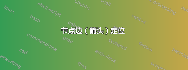
不幸的是,箭头的位置不正确。我想大致保留节点的配置,让一些箭头从节点底部开始(例如节点 (A) 的底部中间)或直接到达底部(例如(从 (C) 到 (G))而不是先水平然后垂直。下图以黑色显示了上述代码的输出;红色显示了我大致想要得到的线条(当然是箭头),尽管如果它使代码更简单、更健壮,我并不十分确定这些确切的线条。

在此先感谢关于如何实现这一点以及修改edge起点和路径的任何建议。
答案1

这是否符合要求——虚线可以用箭头代替
数学家协会
\documentclass[tikz, border=5pt]{standalone}

\usepackage{tikz}

\begin{document}
\begin{tikzpicture}[node distance=2cm]
    % nodes
    \node (A)  at (3.5, 5) {ABC};
    \node (B)   at (3.5, 4) {some slightly longer text in here};
    \node (C)  at (1, 3) {some other thext here};
    \node (D)  at (6, 3) {name of node displayed here};
    \node (E) at (9.5, 2) {name of another node about here};
    \node (F)  at (4, 2.5) {next node's titletext};
    \node (G) at (4, 1) {final node displayed here};

    % arrows
    % \draw[->, to path={-| (\tikztotarget)}]
    % (A) edge (B) (B) edge (C) (C) edge (F)
    %                           (C) edge (G)
    %              (B) edge (D) (D) edge (E) (E) edge (G);
    \draw [thick,dash dot, red] (A) -- (B);
    \draw [thick,dash dot, red] (B) -- (C);
    \draw [thick,dash dot, red] (C) -- (F);
    \draw [thick,dash dot, red] (C) -- (G);
    \draw [thick,dash dot, red] (B) -- (D);
    \draw [thick,dash dot, red] (D) -- (E);
    \draw [thick,dash dot, red] (E) -- (G);

\end{tikzpicture}
\end{document}
编辑
箭头(红色)
对于距离节点 (C) 太近的节点 (D),\xshift添加 4.5

平均能量损失
\documentclass[tikz, border=5pt]{standalone}

\usepackage{tikz}

\begin{document}
\begin{tikzpicture}[node distance=2cm]
    % nodes
    \node (A)  at (3.5, 5) {ABC};
    \node (B)   at (3.5, 4) {some slightly longer text in here};
    \node (C)  at (1, 3) {some other thext here};
    \node (D)  at (6, 3) {name of node displayed here};
    \node (E) at (9.5, 2) {name of another node about here};
    \node (F)  at (4.5, 2) {next node's titletext};
    \node (G) at (4, 1) {final node displayed here};

    % arrows
    % \draw[->, to path={-| (\tikztotarget)}]
    % (A) edge (B) (B) edge (C) (C) edge (F)
    %                           (C) edge (G)
    %              (B) edge (D) (D) edge (E) (E) edge (G);
    \draw [->,thick,dash dot, red] (A) -- (B);
    \draw [->,thick,dash dot, red] (B) -- (C);
    \draw [->,thick,dash dot, red] (C) -- (F);
    \draw [->,thick,dash dot, red] (C) -- (G);
    \draw [->,thick,dash dot, red] (B) -- (D);
    \draw [->,thick,dash dot, red] (D) -- (E);
    \draw [->,thick,dash dot, red] (E) -- (G);

\end{tikzpicture}
\end{document}
编辑
用于Manhattan style混合regular style
节点 H 定义为新的箭头原点
节点 D 向右移动,为从节点 H 向下的箭头腾出空间
平均能量损失
\documentclass[tikz, border=5pt]{standalone}

\usepackage{tikz}

\begin{document}
\begin{tikzpicture}[node distance=2cm]
    % nodes
    \node (A)  at (3.5, 5) {ABC};
    \node (B)   at (3.5, 4) {some slightly longer text in here};
    \node (C)  at (1, 3) {some other thext here};
    \node (D)  at (7, 3) {name of node displayed here};
    \node (E) at (9.5, 2) {name of another node about here};
    \node (F)  at (4.5, 2) {next node's titletext};
    \node (G) at (4, 1) {final node displayed here};
    \node (H) at (3.6,4) {};
    % \node (J) at (3.6,4) {};
    % arrows
    % \draw[->, to path={-| (\tikztotarget)}]
    % (A) edge (B) (B) edge (C) (C) edge (F)
    %                           (C) edge (G)
    %              (B) edge (D) (D) edge (E) (E) edge (G);
    \draw [thick,dash dot, red] (A) -- (B);
    \draw  (B) |- (C);
    \draw [ red] (C) |- (F);
    \draw [->,thick,dash dot, red] (C) |- (G);
    \draw [->,thick, red] (H) |- (D);
    \draw [->,thick,dash dot, red] (D) -- (E);
    \draw [->,thick,dash dot, red] (E) -- (G);

\end{tikzpicture}
\end{document}

答案2
以下是其他一些替代方案:

\documentclass[tikz, border=5pt]{standalone}

\usepackage{tikz}
\usetikzlibrary{positioning}

\begin{document}

    \begin{tikzpicture}[node distance=1cm]
        % nodes
        \node (A)  at (3.5, 5) {ABC};
        \node (B)[below of=A]{some slightly longer text in here};
        \node (C)[below left=  and -1cm of B]{some other thext here};
        \node (D)[below right= and -2cm of B]{name of node displayed here};
        \node (E)[below right= and -2cm of D] {name of another node about here};
        \node (F)[below =2cm of B]{next node's titletext};
        \node (G)[below=of F]{final node displayed here};

        % arrows
        \draw[->](A)--(B);
        \draw[->, to path={-| (\tikztotarget)}](B) edge (C)
                                               (B) edge (D)
                                               (D) edge (E);
        \draw[->, to path={|- (\tikztotarget)}](C) edge (F)
                                               (C) edge (G)
                                               (E) edge (G) ;
    \end{tikzpicture}


\begin{tikzpicture}[node distance=1cm]
    % nodes
    \node (A)  at (3.5, 5) {ABC};
    \node (B)[below of=A]{some slightly longer text in here};
    \node (C)[below left=  and -1cm of B]{some other thext here};
    \node (C1)[right = -1.5cm of C]{\phantom{l}};
    \node (D)[below right= and -2cm of B]{name of node displayed here};
    \node (E)[below right= and -2cm of D] {name of another node about here};
    \node (F)[below =2cm of B]{next node's titletext};
    \node (G)[below=of F]{final node displayed here};

    % arrows
    \draw[->](A)--(B);
    \draw[->, to path={-| (\tikztotarget)}](B) edge (C)
                                           (B) edge (D)
                                           (D) edge (E);
    \draw[->, to path={|- (\tikztotarget)}](C1) edge (F)
                                           (C) edge (G)
                                           (E) edge (G) ;
\end{tikzpicture}


\begin{tikzpicture}[node distance=1cm]
    % nodes
    \node (A)  at (3.5, 5) {ABC};
    \node (B)[below of=A]{some slightly longer text in here};
    \node (Cb)[below= of B.south west]{\phantom{l}};
    \node (C)[below left=  and -1cm of B]{some other thext here};
    \node (C1)[right = -1.5cm of C]{\phantom{l}};
    \node (Cd)[below= of B.south east]{\phantom{l}};
    \node (D)[below right= and -2cm of B]{name of node displayed here};
    \node (De)[below= of D.south east]{\phantom{l}};
    \node (E)[below right= and -2cm of D] {name of another node about here};
    \node (F)[below =2cm of B]{next node's titletext};
    \node (G)[below=of F]{final node displayed here};

    % arrows
    \draw[->](A)--(B);
    \draw[->](B.south west) -- (Cb);
    \draw[->](B.south east) -- (Cd);
    \draw[->](D.south east) -- (De);
    \draw[->, to path={|- (\tikztotarget)}](C1) edge (F)
                                           (C) edge (G)
                                           (E) edge (G) ;
\end{tikzpicture}

\end{document}