

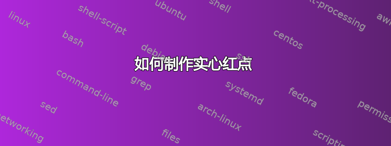
这是我输入的内容。我的红点是透明的。有什么方法可以让它变成实心的,这样你就看不到穿过它的线条了?另外,请随意清理我的代码或进行任何更正。
\documentclass{article}
\usepackage[utf8]{inputenc}
\usepackage[english]{babel}

\usepackage{amsthm}
\usepackage{graphicx}
\usepackage{tikz}
\usepackage{tkz-euclide}
\usepackage[colorinlistoftodos]{todonotes}
\usepackage[colorlinks=true, allcolors=blue]{hyperref}

\newcommand{\vertex}[2]{\filldraw ({#1},{#2}) circle (0.12)}

\definecolor{mygreen1}{RGB}{0,200,0}
\definecolor{mygreen2}{RGB}{0,150,0}
\definecolor{mygreen3}{RGB}{0,100,0}
\definecolor{mygreen4}{RGB}{0,50,0}

\begin{document}


\begin{center}
\begin{tikzpicture}[scale=1.5]
\draw[very thick] (0,0) -- (3,0) -- (2,2) -- (0,0);
\node at (-.25,-0.25) {\Large $A$};
\node at (3.2,-.25) {\Large $B$};
\node at (2,2.3) {\Large $C$};
\node[blue] at (0.65,1.025) {\Large $M$};
\node[blue] at (2.85,1.025) {\Large $N$};
\node[blue] at (1.5,-0.25) {\Large $P$};
\filldraw (1,1) circle (.05);
\filldraw (2.5,1) circle (.05);
\filldraw (1.5,0) circle (.05);
\filldraw[red] (1.67,0.67) circle (.05);
\draw[blue] (1,1) -- (3,0);
\draw[blue] (2.5,1) -- (0,0);
\draw[blue] (1.5,0) -- (2,2);

\tkzDefPoint(0,0){A}
\tkzDefPoint(1.5,0){P}
\tkzDefPoint(3,0){B}
\tkzDefPoint(1,1){M}
\tkzDefPoint(2,2){C}
\tkzDefPoint(2.5,1){N}
\tkzDefPoint(1.5,0){P}

\tkzMarkSegment[mark=|](A,M)
\tkzMarkSegment[mark=|](M,C)
\tkzMarkSegment[mark=||](C,N)
\tkzMarkSegment[mark=||](N,B)
\tkzMarkSegment[mark=|||](A,P)
\tkzMarkSegment[mark=|||](P,B)

\end{tikzpicture}
\end{center}


\end{document}
答案1
我使用 v 3.01 来回答这个问题。问题与 相同,tkz-euclide因为它使用了TikZ的选项。这就是为什么因为 有可能,tkz-euclide我更喜欢这种方法:定义、微积分、绘图、标记标签
用三条线就可以得到所有点!然后你只需要画出...
顺序很重要,你需要用这些点来完成这些点。如果你看一下 pgfmanual“教程:欧几里得的琥珀版《几何原本》”,你会看到这些点被画在最后。
\documentclass{standalone}
\usepackage{tkz-euclide}

\begin{document}
\begin{tikzpicture}[scale=1.5]
  % fixed points
  \tkzDefPoints{0/0/A,3/0/B,2/2/C}
  % calclations
  \tkzDefSpcTriangle[centroid](A,B,C){M,N,P} % centroid or medial
  \tkzDefTriangleCenter[centroid](A,B,C) \tkzGetPoint{G}
  % drawings
  \tkzDrawPolygon[very thick](A,B,C)
  \tkzDrawSegments[blue](A,M B,N C,P)
  \tkzDrawPoints(A,B,C,M,N,P)
  \tkzDrawPoint[fill=red,draw=red](G)
  % marking
  \tkzMarkSegments[mark=|](C,M M,B)
  \tkzMarkSegments[mark=||](A,N N,C)
  \tkzMarkSegments[mark=|||](A,P P,B)
  % labelling
  % you can add some style with
   \tikzset{label style/.append style ={font=\Large}}
  % label style is defined by the package you can refine it
  % or add your own style
  \tkzLabelPoint[below left](A){$A$}
  \tkzLabelPoint[below right](B){$B$}
  \tkzLabelPoint[above](C){$C$}
  \tkzLabelPoint[right](M){$M$}
  \tkzLabelPoint[left](N){$N$}
  \tkzLabelPoint[below](P){$P$}
\end{tikzpicture}
\end{document}
你可以使用pdflatex或进行编译lualatex
您可以使用多种方法获得此处的交点即重心:
\tkzDefTriangleCenter[centroid](A,B,C) \tkzGetPoint{G}你可以medial使用centroid您可以搜索路口
\tkzInterLL(A,M)(B,N) \tkzGetPoint{G}或者使用重心坐标!
\tkzDefBarycentricPoint(A=1,B=1,C=1) \tkzGetPoint{G}我认为 TikZ 是一个很好的解决方案,而不是‘名字可怜’。最后
\tkzDefCentroid(A,B,C) \tkzGetPoint{G}
关于\tkzDefSpcTriangle[centroid](A,B,C){M,N,P}
现在在上一版本中我添加了宏来定义经典三角形和圆形的注释。在这里我们得到了“中间”三角形 (M,N,P)。我更喜欢\tkzDefSpcTriangle[centroid,name=M](A,B,C){a,b,c}并且中点是Ma,Mb,Mc或者\tkzDefSpcTriangle[centroid,name=M](A,B,C){_a,_b,_c}现在中点是新的参考M_a,M_b并且M_c

答案2
您的红色圆圈已经是实心的,您只是碰巧稍后绘制了与其重叠的东西。如果您将语句移到\filldraw[red] (...) circle末尾,一切看起来都很好。
另请注意,的首选语法circle是circle[radius=<dim>]而不是circle(<dim>)。
此外,您应该-- cycle在封闭路径的末端使用,这样就不会得到开放的角落。
在答案中,我将蓝线向上移动,而不是将红点向下移动。我还稍早使用了命名坐标,并重复使用了名称,而不是多次给出相同的坐标。此外,我还使用该intersections库来计算红点的位置。
\documentclass{article}

\usepackage{tikz}
\usetikzlibrary{intersections}
\usepackage{tkz-euclide}

\begin{document}
\begin{tikzpicture}[scale=1.5, every node/.append style={font=\Large}]
  \draw[blue, name path=M--B] (1,1) coordinate(M) -- (3,0) coordinate(B);
  \draw[blue, name path=N--A] (2.5,1) coordinate(N) -- (0,0) coordinate(A);
  \draw[blue] (1.5,0) coordinate(P) -- (2,2) coordinate(C);
  \draw[very thick] (A) -- (B) -- (C) -- cycle;
  \node[below left] at (A) {$A$};
  \node[below right] at (B) {$B$};
  \node[above] at (C) {$C$};
  \node[above left,blue] at (M) {$M$};
  \node[above right,blue] at (N) {$N$};
  \node[below,blue] at (P) {$P$};
  \foreach\x in {P,M,N}
    \filldraw (\x) circle[radius=.05];
  \path[name intersections={of=M--B and N--A,by=Z}];
  \filldraw[red] (Z) circle[radius=.05];

  \tkzMarkSegment[mark=|](A,M)
  \tkzMarkSegment[mark=|](M,C)
  \tkzMarkSegment[mark=||](C,N)
  \tkzMarkSegment[mark=||](N,B)
  \tkzMarkSegment[mark=|||](A,P)
  \tkzMarkSegment[mark=|||](P,B)
\end{tikzpicture}
\end{document}

@Schrödinger'scat 在评论中建议了一个较短的版本。我个人认为较长的版本对于新手来说更容易理解,因此我将较短的版本添加为第二个代码块。
\documentclass{article}

\usepackage{tikz}
\usetikzlibrary{intersections}
\usepackage{tkz-euclide}

\begin{document}
\begin{tikzpicture}[scale=1.5, every label/.style={font=\Large, execute at begin node=$, execute at end node=$}, every circle/.style={radius=.05}]
  \draw[blue, name path=M--B] (1,1) coordinate[label=above left:M](M) -- (3,0) coordinate[label={[black]below right:B}](B);
  \draw[blue, name path=N--A] (2.5,1) coordinate[label=above right:N](N) -- (0,0) coordinate[label={[black]below left:A}](A)
    (1.5,0) coordinate[label=below:P](P) -- (2,2) coordinate[label={[black]above:C}](C);
  \draw[very thick] (A) -- (B) -- (C) -- cycle;
  \path[name intersections={of=M--B and N--A,by=Z}];
  \foreach\x/\y in {/P,/M,/N,red/Z} \filldraw[\x] (\y) circle;

  \tkzMarkSegment[mark=|](A,M)
  \tkzMarkSegment[mark=|](M,C)
  \tkzMarkSegment[mark=||](C,N)
  \tkzMarkSegment[mark=||](N,B)
  \tkzMarkSegment[mark=|||](A,P)
  \tkzMarkSegment[mark=|||](P,B)
\end{tikzpicture}
\end{document}
答案3
这个答案就是简单的 TikZ。不需要其他包或库。

\documentclass[tikz,border=2mm]{standalone}
% pic for marking segments, use with pic options (rotate, thick, red, ...)
% markx    > x
% markl    > |
% markll   > ||
% marklll  > |||
\tikzset{
markx/.pic={\draw (45:.1)--(-135:.1) (-45:.1)--(135:.1);},
markl/.pic={\draw (90:.1)--(-90:.1);},
markll/.pic={\draw[shift={(180:.02)}] (90:.1)--(-90:.1);
             \draw[shift={(0:.02)}] (90:.1)--(-90:.1);},
marklll/.pic={\draw[shift={(180:.03)}] (90:.1)--(-90:.1);
              \draw (90:.1)--(-90:.1);
              \draw[shift={(0:.03)}] (90:.1)--(-90:.1);}
}
%%%%%%%%%%%%%%%%%%%%%%%%%%%
\begin{document}
\begin{tikzpicture}
\path
(-1,0)   coordinate (A) node[below left]{$A$}
(4,0)    coordinate (B) node[below right]{$B$}
(0,3.5)  coordinate (C) node[above]{$C$}
(A)--(B) coordinate[pos=.5] (M) (M) node[below]{$M$}
(B)--(C) coordinate[pos=.5] (N) (N) node[above right]{$N$}
(C)--(A) coordinate[pos=.5] (P) (P) node[above left]{$P$};

\draw[gray] (A)--(N) (B)--(P) (C)--(M);
\draw (A)--(B)--(C)--cycle;

% markings
\path
(A)--(B) pic[pos=.25,red]{markx} pic[pos=.75,red]{markx}
(B)--(C) pic[pos=.25,rotate=-30]{markll} pic[pos=.75,rotate=-30]{markll}
(C)--(A) pic[pos=.25,blue,thick,rotate=45]{markl} pic[pos=.75,blue,thick,rotate=45]{markl};

% G is the centroid of triangle ABC
\path (barycentric cs:A=1,B=1,C=1) coordinate (G);

% fill points with solid dots
\fill[magenta] (G) circle(1.5pt) +(-110:.3) node{$G$};
\foreach \p in {A,B,C,M,N,P}
\fill (\p) circle(1.5pt);
%\draw[fill=white] (\p) circle(1.5pt);
\end{tikzpicture}
\end{document}
答案4
只是为了好玩。
import psteuclasy;// https://github.com/justonly011298/psteuclasy
size(300);
defaultpen(linewidth(0.3mm));

pair A=(0,0),B=(3,0),C=(2,2);
pair M=pstMiddleAB(B,C),N=pstMiddleAB(A,C),P=pstMiddleAB(B,A);
draw(A--B--C--cycle);
pstSegmentMark(B--M^^M--C,invisible,MarkHash(angle=0));
pstSegmentMark(A--N^^N--C,invisible,MarkHashh(angle=0));
pstSegmentMark(A--P^^P--B,invisible,MarkHashhh(angle=0));
draw(A--M^^B--N^^C--P,blue);
dot("A",A,SW);
dot("B",B,SE);
dot("C",(2,2),-S); // N = Relative((0,1)) = -S
dot("M",M,E);
dot("N",N,W);
dot("P",P,S);
dot(pstCGravABC(A,B,C),red);
