


我很抱歉提出这个问题,但我已经挣扎了 5 个小时,而且我做得一点也不好。我知道这方面还有其他问题,我尝试使用 tikz,但是当我从这个站点中获取示例并尝试删除/添加节点时,结果看起来一点也不好。
\begin{tikzpicture}[ 缩短 >=1pt,->, draw=black!1000, 节点距离=\layersep, 每个引脚边缘/.style={<-,缩短 <=1pt}, 神经元/.style={circle,draw,最小尺寸=17pt,inner sep=0pt}, 输入神经元/.style={neuron}, 输出神经元/.style={neuron}, 隐藏神经元/.style={neuron}, annot/.style={text width=4em, 文本居中} ]
% Draw the input layer nodes
\foreach \name / \y in {1,...,3}
% This is the same as writing \foreach \name / \y in {1/1,2/2,3/3,4/4}
    \node[input neuron, pin=left:Input \#\y] (I-\name) at (0,-\y) {};

% set number of hidden layers
\newcommand\Nhidden{2}

% Draw the hidden layer nodes
\foreach \N in {1,...,\Nhidden} {
   \foreach \y in {1,...,2} {
      \path[yshift=0.5cm]
          node[hidden neuron] (H\N-\y) at (\N*\layersep,-\y cm) {};
       }
\node[annot,above of=H\N-1, node distance=1cm] (hl\N) {Hidden layer \N};
}

% Draw the output layer node
\node[output neuron,pin={[pin edge={->}]right:Output}, right of=H\Nhidden-3] (O) {};

% Connect every node in the input layer with every node in the
% hidden layer.
\foreach \source in {1,...,3}
    \foreach \dest in {1,...,2}
        \path (I-\source) edge (H1-\dest);

% connect all hidden stuff
\foreach [remember=\N as \lastN (initially 1)] \N in {2,...,\Nhidden}
   \foreach \source in {1,...,3}
       \foreach \dest in {1,...,3}
           \path (H\lastN-\source) edge (H\N-\dest);

% Connect every node in the hidden layer with the output layer
\foreach \source in {1,...,3}
    \path (H\Nhidden-\source) edge (O);

% Annotate the layers

\node[annot,left of=hl1] {Input layer};
\node[annot,right of=hl\Nhidden] {Output layer};
\end{tikzpicture}
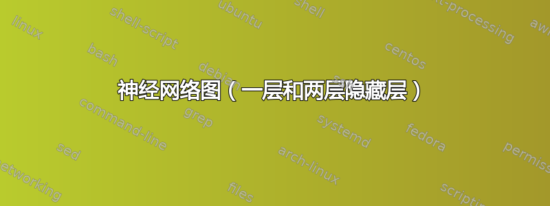
此代码用于第二张图...结果是:

答案1
第一个神经图 --- 原始代码发布于 2006-12-07 | 作者:Kjell Magne Fauske-- texample.net/tikz/examples/neural-network

\documentclass{article}

\usepackage{tikz}
\begin{document}
\pagestyle{empty}

\def\layersep{2.5cm}

\begin{tikzpicture}[shorten >=1pt,->,draw=black!50, node distance=\layersep]
    \tikzstyle{every pin edge}=[<-,shorten <=1pt]
    \tikzstyle{neuron}=[circle,fill=black!25,minimum size=17pt,inner sep=0pt]
    \tikzstyle{input neuron}=[neuron, fill=green!50];
    \tikzstyle{output neuron}=[neuron, fill=red!50];
    \tikzstyle{hidden neuron}=[neuron, fill=blue!50];
    \tikzstyle{annot} = [text width=4em, text centered]

    % Draw the input layer nodes
    \foreach \name / \y in {1,...,3}
    % This is the same as writing \foreach \name / \y in {1/1,2/2,3/3,4/4}
        \node[input neuron, pin=left:Input \#\y] (I-\name) at (0,-\y) {};

    % Draw the hidden layer nodes
    \foreach \name / \y in {1,...,3}
        \path[yshift=0.0cm]
            node[hidden neuron] (H-\name) at (\layersep,-\y cm) {};

    % Draw the output layer node
    \node[output neuron,pin={[pin edge={->}]right:Output}, right of=H-2] (O) {};

    % Connect every node in the input layer with every node in the
    % hidden layer.
    \foreach \source in {1,...,3}
        \foreach \dest in {1,...,3}
            \path (I-\source) edge (H-\dest);

    % Connect every node in the hidden layer with the output layer
    \foreach \source in {1,...,3}
        \path (H-\source) edge (O);

    % Annotate the layers
    \node[annot,above of=H-1, node distance=1cm] (hl) {Hidden layer};
    \node[annot,left of=hl] {Input layer};
    \node[annot,right of=hl] {Output layer};
\end{tikzpicture}
% End of code
\end{document}
编辑——第二个神经图

\documentclass{article}

\usepackage{tikz}
\begin{document}
\pagestyle{empty}

\def\layersep{2.5cm}

\begin{tikzpicture}[shorten >=1pt,->,draw=black!50, node distance=\layersep]
    \tikzstyle{every pin edge}=[<-,shorten <=1pt]
    \tikzstyle{neuron}=[circle,fill=black!25,minimum size=17pt,inner sep=0pt]
    \tikzstyle{input neuron}=[neuron, fill=green!50];
    \tikzstyle{output neuron}=[neuron, fill=red!50];
    \tikzstyle{hidden neuron}=[neuron, fill=blue!50];
    \tikzstyle{annot} = [text width=4em, text centered]

    % Draw the input layer nodes
    \foreach \name / \y in {1,...,3}
    % This is the same as writing \foreach \name / \y in {1/1,2/2,3/3,4/4}
        \node[input neuron, pin=left:Input \#\y] (I-\name) at (0,-\y) {};


%--------------------------------------------------------------------------------------
% Draw the input layer nodes
\foreach \name / \y in {1,...,2}
% This is the same as writing \foreach \name / \y in {1/1,2/2,3/3,4/4}
\node[hidden neuron] (J-\name) at (\layersep,-\y cm) {};
%------------------------------------------------------------------------------


%    % Draw the hidden layer nodes
    \foreach \name / \y in {1,...,3}
        \path[yshift=0.0cm]
            node[hidden neuron] (H-\name) at (2*\layersep,-\y cm) {};
%
%    % Draw the output layer node
    \node[output neuron,pin={[pin edge={->}]right:Output}, right of=H-2] (O) {};
%
%    % Connect every node in the input layer with every node in the
%    % hidden layer.
    \foreach \source in {1,...,3}
        \foreach \dest in {1,...,2}
            \path (I-\source) edge (J-\dest);
%

 \foreach \source in {1,...,2}
\foreach \dest in {1,...,3}
\path (J-\source) edge (H-\dest);


%    % Connect every node in the hidden layer with the output layer
    \foreach \dest in {1,..,2}
    \foreach \source in {1,...,3}
        \path (H-\source) edge (O);
%
%    % Annotate the layers
    \node[annot,above of=H-1, node distance=1cm] (hl) {Hidden layer};
    \node[annot,left of=hl,xshift=-2.5cm] {Input layer};
    \node[annot,right of=hl] {Output layer};
\end{tikzpicture}
% End of code
\end{document}