

我正在尝试使用改编自我之前的 Tikz 代码执行以下操作问题1和问题2 我正在修改的代码归功于@Zarko:
\documentclass{scrartcl}
\usepackage{tikz}
\usetikzlibrary{arrows.meta,
                chains,
                decorations.pathreplacing,calligraphy,
                positioning,
                quotes,
                shapes.geometric
                }
\begin{document}
\begin{center}

 \begin{tikzpicture}[auto,
    node distance = 6mm and 15mm,
      start chain = A going below,
       arr/.style = {-Stealth},
every edge/.style = {draw, arr},
        BC/.style = {decorate,  % Brace Calligraphic
                     decoration={calligraphic brace, amplitude=3mm,
                                 raise=1mm, mirror},
                     very thick, pen colour={black}
                    },
       box/.style = {draw, rounded corners, fill=blue!20, align=center,
                     minimum height=4em, text width=6em},
  decision/.style = {diamond, aspect=1.5, draw, fill=blue!20,
                    inner xsep=-3pt, text width=5.4em, align=center},
                        ]
 ellipse/.style = { ellipse, aspect=1.5,draw, fill=blue!20,
                    inner xsep=-3pt, text width=5.4em, align=center},
                        ]
% nodes
    \begin{scope}[nodes={on chain=A, join=by arr}]
\node   [ellipse]       {Initiate};     % name=A-1
\node   [box]       { Program Kernel};
\node   [box]  {Data Distribution};
\node   [box]       {Accept $S_{n+1}$};
\node   [box]       {$T_{n+1} = K(T_n)$ and $n=n+1$};
\node   [decision]  {Stop?};                            % A-6
    \end{scope}
% nodes in right column
\node   [box, right=of A-2] (rej) {Prior Data};
\node   [box, at={(A-6 -| rej)}] (stop) {Stop};
% edge labels and connections not considered in join macro
\path

        (A-6)   edge ["yes"]  (stop);
\draw[arr]  (rej) -- node[auto]    {$D_1$} (A-2);
\draw[arr]  (A-6.west) to ["no" '] ++(-1,0) |- (A-2);
% braces
\draw[BC]   ([xshift=-12mm] A-1.north west) coordinate (aux) --
                    node[midway,left=5mm]{Stage 1}
            (aux |- A-4.south);
\draw[BC]   (aux |- A-5.north) --
                    node[midway,left=5mm]{Stage 2}
            (aux |- A-6.south);
\end{tikzpicture}
    \end{center}
\end{document}

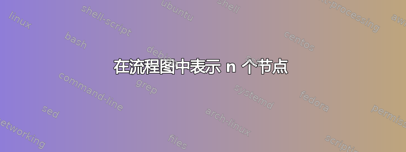
但是,尽管在样式中添加了椭圆,并在水平方向添加了多个节点,中间有显示 n 个块的小圆圈,但我无法在开始时获得圆圈。以下是我想要实现的目标。

答案1
一个粗鲁的完整解决方案:

存在更优雅的代码......
\documentclass{ieeetran}
\usepackage{tikz}
\usetikzlibrary{arrows.meta,
                chains,
                decorations.pathreplacing,calligraphy,
                fit,
                positioning,
                quotes,
                shapes.geometric
                }
\makeatletter
\tikzset{
    suspend join/.code = {\def\tikz@after@path{}}
        }
\makeatother
\usepackage{lipsum}

\begin{document}
\lipsum[11]
    \begin{figure}[ht]
    \centering
\begin{tikzpicture}[auto,
    node distance = 3mm and 2mm,
      start chain = A going below,
       arr/.style = {-Stealth},
every edge/.style = {draw, arr},
        BC/.style = {decorate,  % Brace Calligraphic
                     decoration={calligraphic brace, amplitude=2mm,
                                 raise=1mm, mirror},
                     very thick, pen colour={black}
                    },
       box/.style = {draw, rounded corners, fill=blue!20, align=center,
                     minimum height=5ex, text width=#1},
box/.default = 5.5em,
  decision/.style = {diamond, aspect=1.5, draw, fill=blue!20,
                    inner xsep=-3pt, minimum width=5.4em, align=center},
    ellip/.style = { ellipse, aspect=1.5,draw, fill=blue!20,
                    inner xsep=-3pt, text width=5.4em, align=center},
                        ]
% nodes in chain
    \begin{scope}[nodes={on chain=A, join=by arr}]
\node   [ellip]     {Initiate};         % name=A-1
\node   [box]       {Program Kernel};
\node   [box]       {Data Distribution};
\node   [suspend join,
         font=\bfseries,
         below=12mm]    {\dots};        % A-4
    \end{scope}
% nodes in the left column
\node   [box=4em, left=of A-4] (p2) {Procesor 2};
\node   [box=4em, left=of p2]  (p1) {Procesor 1};
% nodes in the right column
\node   [box=4em, right=of A-4] (pn) {Procesor $n$};
% nodes in the main column
\node   [box, fit=(p1) (pn),
         below right=8mm and 0mm of p1.south west,
         label=center:Main server] (ms) {};
\node   [decision, below=of A-4 |- ms.south]    (ptc)
                               {Packet Transfer\\ Complete?};
% nodes in the left
\node   [box=4em, at={(p1 |- A-2)}] (ld)  {Load Data};
\node   [box, at={(p1 |- ptc)}]  (stop) {Continue};
% edge labels and connections not considered in join macro
\draw[arr]  (ld)   to["$D_1$"]     (A-2);
    \foreach \i in {p1, p2, pn}
{
\draw[arr] (A-3) -- (\i);
\draw[arr] (\i) -- (\i |- ms.north);
}
\draw[arr]  (ms.south -| ptc)   to  (ptc);
\draw[arr]  (ptc)   to["no" ']        (stop);
\draw[arr]  (ptc.east) to ["yes"] ++(1,0) |- (A-2);
% braces
\draw[BC]   (p1.north west) --
                    node[left=3mm]{Stage 2}
            (p1.south west);
\draw[BC]   (p1.west |- ld.north) --
                    node[left=3mm]{Stage 1}
            (A-3.south -| ms.west);

\end{tikzpicture}
    \end{figure}
\lipsum
\end{document}
答案2
不建议命名风格确切地作为形状的名称,TikZ 将无法区分两者。因此,您应该更改ellipse为其他名称,因为此名称已经标识了形状本身。
通过将样式从选项中移出tikzpicture并移到\tikzset类似下面的样子,您的问题就可以轻松解决:
\tikzset{
    elli/.style={ellipse, aspect=1.5,draw, fill=blue!20,
                    inner xsep=-3pt, text width=5.4em, align=center},
}
结果如下:
