

我是这个 latex 论坛的新手,在在线平台的帮助下尝试为我的工作创建流程图。代码如下。如果以下代码能够修正以满足我的需求,那将是一个很大的帮助。提前致谢。

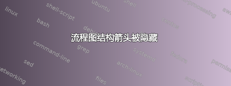
- 我希望流程图位于中心。
- 连接文本框6-8和8-9的箭头不应重叠。
- 文本框 16-2 之间的箭头连接器应该可见,并且带有“YES”注释。
\documentclass{article}
\usepackage[latin1]{inputenc}
\usepackage{tikz}
\usetikzlibrary{shapes,arrows}
\begin{document}
\pagestyle{empty}
% Define block styles
\tikzstyle{startstop} = [rectangle, rounded corners, minimum width=3cm, minimum height=1cm,text centered, draw=black, fill=red!30]
\tikzstyle{io} = [trapezium, trapezium left angle=70, trapezium right angle=110, minimum width=3cm, minimum height=1cm, text centered, draw=black, fill=blue!30]
\tikzstyle{process} = [rectangle, minimum width=3cm, minimum height=1cm, text centered,text width=3cm, draw=black, fill=orange!30]
\tikzstyle{decision} = [diamond, minimum width=1.5cm, minimum height=0.5cm, text centered,text width=1.5cm,draw=black, fill=green!30]
\tikzstyle{arrow} = [thick,->,>=stealth]
\tikzstyle{line} = [thick,->,>=stealth]

\begin{tikzpicture}[node distance=2cm]
\node (start) [startstop] {Start};
\node (pro1) [process, below of=start] {1};
\node (pro2) [process, below of=pro1,yshift=-0.5cm] {2};
\node (pro2a) [process, left of=pro2,xshift=-2.5cm] {3};
\node (pro3) [process, below of=pro2,yshift=-0.5cm] {4};
\node (pro3a) [process, left of=pro3,xshift=-2cm] {5};
\node (pro3b) [process, right of=pro3,xshift=2cm] {6};
\node (pro3c) [process, right of=pro3b,xshift=1.5cm] {7};
\node (pro4) [process, below of=pro3,xshift=2cm] {8};
\node (pro4a) [process, right of=pro4,xshift=2.5cm] {9};
\node (pro5) [process, below of=pro4] {10};
\node (pro6) [process, below of=pro5,yshift=-0.5cm] {11};
\node (pro7) [process, below of=pro4a,yshift=-1.5cm] {12};
\node (pro8) [process, below of=pro6,yshift=-0.5cm] {13};
\node (pro8a) [process, below of=pro7,yshift=-1.5cm] {14};
\node (pro9) [process, below of=pro8a,yshift=-0.5cm] {15};
\node (dec1) [decision, below of=pro9,yshift=-1cm] {16};
\node (stop)[startstop, below of=dec1,yshift=-1cm] {stop};

\draw [arrow] (start) -- (pro1);
\draw [arrow] (pro1) -- (pro2);
\draw [arrow] (pro1) -|(pro2a);
\draw [arrow] (pro2a) -- (pro2);
\draw [arrow] (pro2) -- (pro3);
\draw [arrow] (pro3a) -- (pro3);
\draw [arrow] (pro3) -- (pro3b);
\draw [arrow] (pro3c) -- (pro3b);
\draw [arrow] (pro3) |- (pro4);
\draw [arrow] (pro3b)|- (pro4);
\draw [arrow] (pro4)-- (pro4a);
\draw [arrow] (pro4)-- (pro5);
\draw [arrow] (pro5)-- (pro6);
\draw [arrow] (pro4a)-- (pro7);
\draw [arrow] (pro6)-- (pro8);
\draw [arrow] (pro8)-- (pro8a);
\draw [arrow] (pro7)-- (pro8a);
\draw [arrow] (pro8a)-- (pro9);
\draw [arrow] (pro9)-- (dec1);
\draw [arrow] (dec1) -- node[anchor=east] {NO}(stop);
\draw [arrow] (dec1) -- +(6,0)|-(pro2);
\end{tikzpicture}
\end{document}
答案1
我做了什么:
- 我使用列出的一些技术缩小了整个流程图这里。我假设边距为 1 英寸,但如果边距不同,您可以更改比例数字。我还使用了
figure环境,带有\centering。 - 我在库的帮助下改变了两个箭头的起点和终点
calc。 - 我做了一些技巧,你可以在我用来绘制箭头的命令中看到它。
\documentclass{article}
\usepackage[latin1]{inputenc}
\usepackage{tikz}
\usepackage[margin=1in]{geometry}
\usetikzlibrary{shapes,arrows,calc}
\begin{document}
\pagestyle{empty}
% Define block styles
\tikzstyle{startstop} = [rectangle, rounded corners, minimum width=3cm, minimum height=1cm,text centered, draw=black, fill=red!30]
\tikzstyle{io} = [trapezium, trapezium left angle=70, trapezium right angle=110, minimum width=3cm, minimum height=1cm, text centered, draw=black, fill=blue!30]
\tikzstyle{process} = [rectangle, minimum width=3cm, minimum height=1cm, text centered,text width=3cm, draw=black, fill=orange!30]
\tikzstyle{decision} = [diamond, minimum width=1.5cm, minimum height=0.5cm, text centered,text width=1.5cm,draw=black, fill=green!30]
\tikzstyle{arrow} = [thick,->,>=stealth]
\tikzstyle{line} = [thick,->,>=stealth]
\begin{figure}
\centering
\begin{tikzpicture}[node distance=2cm,scale=0.75,transform shape,font=\Large]
\node (start) [startstop] {Start};
\node (pro1) [process, below of=start] {1};
\node (pro2) [process, below of=pro1,yshift=-0.5cm] {2};
\node (pro2a) [process, left of=pro2,xshift=-2.5cm] {3};
\node (pro3) [process, below of=pro2,yshift=-0.5cm] {4};
\node (pro3a) [process, left of=pro3,xshift=-2cm] {5};
\node (pro3b) [process, right of=pro3,xshift=2cm] {6};
\node (pro3c) [process, right of=pro3b,xshift=1.5cm] {7};
\node (pro4) [process, below of=pro3,xshift=2cm] {8};
\node (pro4a) [process, right of=pro4,xshift=2.5cm] {9};
\node (pro5) [process, below of=pro4] {10};
\node (pro6) [process, below of=pro5,yshift=-0.5cm] {11};
\node (pro7) [process, below of=pro4a,yshift=-1.5cm] {12};
\node (pro8) [process, below of=pro6,yshift=-0.5cm] {13};
\node (pro8a) [process, below of=pro7,yshift=-1.5cm] {14};
\node (pro9) [process, below of=pro8a,yshift=-0.5cm] {15};
\node (dec1) [decision, below of=pro9,yshift=-1cm] {16};
\node (stop)[startstop, below of=dec1,yshift=-1cm] {stop};

\draw [arrow] (start) -- (pro1);
\draw [arrow] (pro1) -- (pro2);
\draw [arrow] (pro1) -|(pro2a);
\draw [arrow] (pro2a) -- (pro2);
\draw [arrow] (pro2) -- (pro3);
\draw [arrow] (pro3a) -- (pro3);
\draw [arrow] (pro3) -- (pro3b);
\draw [arrow] (pro3c) -- (pro3b);
\draw [arrow] (pro3) |- (pro4);
\draw [arrow] (pro3b)|- ($(pro4.east)+(0,.2)$);
\draw [arrow] ($(pro4.east)+(0,-.2)$)-- ($(pro4a.west)+(0,-.2)$);
\draw [arrow] (pro4)-- (pro5);
\draw [arrow] (pro5)-- (pro6);
\draw [arrow] (pro4a)-- (pro7);
\draw [arrow] (pro6)-- (pro8);
\draw [arrow] (pro8)-- (pro8a);
\draw [arrow] (pro7)-- (pro8a);
\draw [arrow] (pro8a)-- (pro9);
\draw [arrow] (pro9)-- (dec1);
\draw [arrow] (dec1) -- node[anchor=east] {NO}(stop);
\draw [thick] (dec1) -- ($(dec1)+(6,0)$) coordinate (x);
\draw [arrow] (x)--(x|-pro2) node[midway,right] {YES}--(pro2);
\end{tikzpicture}
\caption{Caption}
\label{fig:my_label}
\end{figure}
\end{document}

(在新标签页中打开图片可以更清晰地查看)
但是,你不应该\tikzstyle再使用了。因此,我认为你的Define block styles部分应该改为
\tikzset{
    startstop/.style={rectangle, rounded corners, minimum width=3cm, minimum height=1cm,text centered, draw=black, fill=red!30},
    io/.style={trapezium, trapezium left angle=70, trapezium right angle=110, minimum width=3cm, minimum height=1cm, text centered, draw=black, fill=blue!30},
    process/.style={rectangle, minimum width=3cm, minimum height=1cm, text centered,text width=3cm, draw=black, fill=orange!30},
    decision/.style={diamond, minimum width=1.5cm, minimum height=0.5cm, text centered,text width=1.5cm,draw=black, fill=green!30},
    arrow/.style={thick,-stealth},
    line/.style={thick,-stealth}
}
答案2
- 作为起点@JouleV 的回答
- 使用的是最近的
tikz语法 用于定位节点的
tikz库positioning及其语法(注意,... of = ...其中使用的是而不是... = of ...。使用该包的语法的
positioning优点是它定义了节点之间的距离。因此,所有节点定位的局部移动都变得多余。- 删除的是缩放
- 字体大小变为正常大小(因为解决方案中没有使用任何缩放)
- 对于直线使用命令
edge(而不是--) - 流程图元素的样式经过了轻微的重组和改进,并被收集在“流程图”样式中,并移至文档序言中(您可以选择其他样式名称),现在可供文档中的任何其他流程图使用(如果存在)
考虑到上述变化,流程图的代码更短(在我看来)更清晰
\documentclass{article}
\usepackage[utf8]{inputenc}
\usepackage[margin=1in]{geometry}
\usepackage{tikz}
\usetikzlibrary{arrows.meta, calc, positioning, shapes.geometric}

\tikzset{FlowChart/.style={
     base/.style = {draw,
                    minimum width=24mm, minimum height=8mm, inner sep=1mm, % you can increase node shape size
                    text width=\pgfkeysvalueof{/pgf/minimum width} -2*\pgfkeysvalueof{/pgf/inner xsep},
                    align=center},
startstop/.style = {base, fill=red!30, rounded corners},
       io/.style = {base, fill=blue!30,
                    trapezium, trapezium stretches body,
                    trapezium left angle=70, trapezium right angle=110,
                    },
  process/.style = {base, fill=orange!30},
 decision/.style = {base, diamond,  aspect=1.3, draw, fill=green!30},
    arrow/.style = {thick,-Stealth},
                            }% end of FlowChart style
        }% end of tikzset

\begin{document}
\pagestyle{empty}
\begin{figure}
\centering
    \begin{tikzpicture}[FlowChart,
    node distance = 5mm and 8mm,
       lbl/.style = {font=\footnotesize}
                        ]
\node (start) [startstop] {Start};
\node (pro1)  [process, below = of start] {1};
\node (pro2)  [process, below = of pro1] {2};
\node (pro2a) [process, left = of pro2] {3};
\node (pro3)  [process, below = of pro2] {4};
\node (pro3a) [process, left = of pro3] {5};
\node (pro3b) [process, right = of pro3] {6};
\node (pro3c) [process, right = of pro3b] {7};
\node (pro4)  [process, below = of $(pro3.south)!0.5!(pro3b.south)$] {8};
\node (pro4a) [process, right = of pro4] {9};
\node (pro5)  [process, below = of pro4] {10};
\node (pro6)  [process, below = of pro5] {11};
\node (pro7)  [process, below = of pro4a] {12};
\node (pro8)  [process, below = of pro6] {13};
\node (pro8a) [process, right = of pro8] {14};
\node (pro9)  [process, below = of pro8a] {15};
\node (dec1)  [decision, below = of pro9] {16};
\node (stop)  [startstop, below = of dec1] {stop};
% connection lines drawnby "edge"
\draw [arrow]   (start) edge (pro1)
                (pro1)  edge (pro2)
                (pro2a) edge (pro2)
                (pro2)  edge (pro3)
                (pro3a) edge (pro3)
                (pro3)  edge (pro3b)
                (pro3c) edge (pro3b)
                ($(pro4.east)+(0,-.2)$) edge ($(pro4a.west)+(0,-.2)$)
                (pro4)  edge (pro5)
                (pro5)  edge (pro6)
                (pro4a) edge (pro7)
                (pro6)  edge (pro8)
                (pro8)  edge (pro8a)
                (pro7)  edge (pro8a)
                (pro8a) edge (pro9)
                (pro9)  edge (dec1)
                (dec1) -- node[lbl, left] {NO} (stop);
% conection linnes with orthogonal paths
\coordinate[right= of pro3c] (x);
\draw [arrow] (pro1) -| (pro2a);
\draw [arrow] (pro3) |- (pro4);
\draw [arrow] (pro3b)|- ($(pro4.east)+(0,.2)$);
\draw [arrow] (dec1) -| node[lbl, pos=0.75,right] {YES} (x) |- (pro2);
\end{tikzpicture}
\caption{Caption}
\label{fig:my_label}
\end{figure}
\end{document}

(红线表示文字边框)