

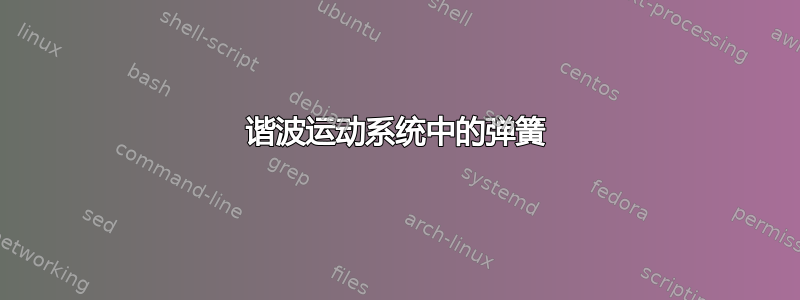
这是我在测验中画的弹簧,但它没有优化。你能帮助改进代码吗?
\documentclass{standalone}
\usepackage{tikz}

\usetikzlibrary{shapes.geometric,calc, angles}
\usetikzlibrary{shapes.geometric,calc, intersections}
\usetikzlibrary{decorations.pathmorphing,patterns}
\usetikzlibrary{decorations.markings}


\begin{document}

\begin{tikzpicture}
    \foreach\x in{-.6,-.56,..., .5} \draw[thin](\x,.23) --(\x+.1,0);
    \draw(-.65,0)--(.65,0);

    \begin{scriptsize}
        \def\d{2.5}

        \draw[decoration={aspect=0.34, segment length=1.05mm, amplitude=1.mm,coil},decorate] (.11,-.3)coordinate(X0) -- (1.4,-1.3*\d) coordinate(X1);


        \draw(X1)--++(.1,-.3);

        \draw[ball color=yellow](X1)++(.068,-.17) coordinate(X2) circle(.18);

        \draw[dashed, thin](X2)--++(1.3, .63) coordinate(X4);
        \draw[dashed, thin](0,0)--++(1.2,.6) coordinate(X3);

        \draw[<->](X3)--(X4) node[midway, fill=white] {10.8 cm};

        \draw[dashed, red](-0,-\d-.85) ellipse(1.46 cm and .3cm);


        \draw[dashed, pink, thin](-0,-\d-.85) ellipse(1.46 cm and .3cm);

        \draw[<-] (0,-\d-.3) arc(88:110:2cm and 1cm);

        \draw(X0)--(0,0);
        \draw(0,-\d-.85)--++(-1.46,0) node[midway, fill=white] {$r$};

        \draw(-1.3,-2.5)node[above] {path of sphere}--++(.2,-.6);
        \draw[dashed](0,1.5)coordinate(T1)--(0,-2);

        \coordinate(T0) at(0,0);
        \coordinate(T2) at(-.42,.95);

        \draw(T1)--(T0)--(T2)pic[draw=blue,->,angle eccentricity=1,angle radius=.75cm] {angle=T1--T0--T2};

        \path(T0)--++(-.25,1.3) node{$27^\circ$};


    \end{scriptsize}

\end{tikzpicture}

\end{document}

答案1
一些建议。
我删除了序言中的重复内容
我将较长的样式语句移到了开头。这样可使以下代码更具可读性,而且即使每个样式只使用一次,最好只在此处进行更改。
记录代码是一种很好的态度。至少下次我重新使用代码时我会忘记所有的细节……
我认为引入 s 作为一种标准化方式没有多大价值
\pic:几乎没有元素被使用两次。但是,我建议将它们的顺序改为更合乎逻辑的顺序,例如首先是图纸,最后是标签。现在,它们相当混杂。我会尝试找到更好的代码分组。角度
27deg可能是重构的目标:您不仅要在顶部标记它,它还会影响弹簧和球。这建议改用一些极坐标,例如(27:5cm)。我还开始重新格式化一些行,使差异一目了然。这与个人喜好有很大关系。但是,如果做得正确,错误会更容易发现、预防和纠正。
\documentclass{standalone}
\usepackage{tikz}

\usetikzlibrary{shapes.geometric,calc, angles}
%\usetikzlibrary{shapes.geometric,calc, intersections} % duplicates
\usetikzlibrary{intersections}
\usetikzlibrary{decorations.pathmorphing,patterns}
\usetikzlibrary{decorations.markings}


\begin{document}

\begin{tikzpicture}[% refactoring styles here
        dt/.style={dashed, thin,teal},
        angl/.style={draw=blue,->,angle eccentricity=1,angle radius=.75cm},
        spring/.style={decoration={
                                    aspect=0.34,
                                    segment length=1.05mm,
                                    amplitude=1.mm,
                                    coil}
                        ,decorate},
        bll/.style={ball color=yellow},
    ]
    % ~~~ hatches ~~~~~~~~~~~~~~~~~
    \foreach\x in{-.6,-.56,..., .5} \draw[thin](\x,.23) --(\x+.1,0);
    \draw(-.65,0)--(.65,0);

    \begin{scriptsize}
        \def\d{2.5}

        % ~~~ spring ~~~~~~~~~~~~~
        \draw[spring] (.11,-.3) coordinate(X0) -- (1.4,-1.3*\d) coordinate(X1);

        % ??
        \draw (X1) -- ++(.1,-.3);

        % ~~~ ball ~~~~~
        \draw[bll] (X1) ++ (.068,-.17) coordinate(X2) circle(.18);

        % ~~~ for the spring dimensions ~~~~~
        \draw[dt](X2)  -- ++(1.3, .63) coordinate(X4);
        \draw[dt](0,0) -- ++(1.2, .6 ) coordinate(X3);

        \draw[<->](X3)--(X4) node[midway, fill=white] {10.8 cm};

        % ~~~ region, where the ball will move ~~~~~~~~~~~
        \draw[dashed, red]  (-0,-\d-.85) ellipse(1.46 cm and .3cm);
        \draw[dt,pink]      (-0,-\d-.85) ellipse(1.46 cm and .3cm);

        % ~~~ the curved arrow (certainly with a purpose) ~~~~~~~~~
        \draw[<-] (0,-\d-.3) arc(88:110:2cm and 1cm);

        \draw(X0)--(0,0);
        \draw(0,-\d-.85)--++(-1.46,0) node[midway, fill=white] {$r$};

        \draw           (-1.3,-2.5) node[above] {path of sphere}--++(.2,-.6);
        \draw[dashed]   (   0, 1.5) coordinate(T1) -- (0,-2);

        \coordinate(T0) at(0,0);
        \coordinate(T2) at(-.42,.95);

        \draw(T1)--(T0)--(T2)pic[angl] {angle=T1--T0--T2};

        \path(T0)--++(-.25,1.3) node{$27^\circ$};
    \end{scriptsize}

\end{tikzpicture}

\end{document}