

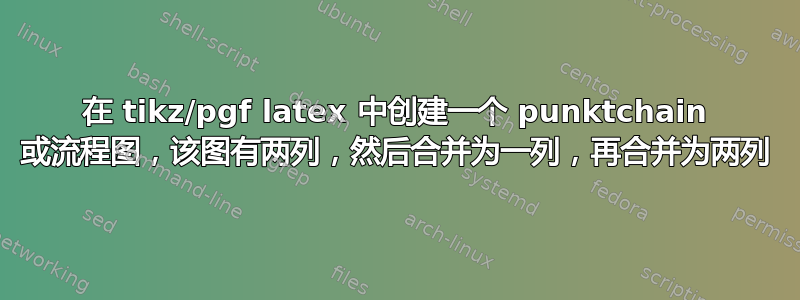
我已经更新了示例代码,添加了一些注释,以便真正接近我想要的效果。现在我只想要两条线从过滤器 1 和过滤器 2 内联出来,并且具有与较小块中已有的相同的线样式。我认为这应该相对容易,但我只能弄清楚如何将线从块的中心移出。
\makeatletter
\tikzset{west above/.code=\tikz@lib@place@handle@{#1}{south west}{0}{1}{north west}{1}}
\tikzset{west below/.code=\tikz@lib@place@handle@{#1}{north west}{0}{-1}{south west}{1}}
\tikzset{east above/.code=\tikz@lib@place@handle@{#1}{south east}{0}{1}{north east}{1}}
\tikzset{east below/.code=\tikz@lib@place@handle@{#1}{north east}{0}{-1}{south east}{1}}
\makeatother
\fontsize{8pt}{9pt}\selectfont
\begin{tikzpicture}[
  every node/.style={
    rectangle,
    rounded corners,
    % fill=black!10,
    draw=black, very thick,
    minimum height=2em,
    inner sep=2pt,
    text centered,
    align=center
  },
  big node/.style={text width=8cm},
  small node/.style={text width=3.5cm},
  >=latex, %Make the arrow tips latex
  myline/.style={draw, very thick,black, <-, node distance=1.1cm},
  mylinedot/.style={draw, very thick, blue!100!black!70, densely dotted, <-, node distance=1cm},
  shorter/.style={shorten <=1mm,shorten >=0.5mm},
  node distance=0.75cm,
  |*/.style={to path=(\tikztostart.south) -- (\tikztostart.south|-\tikztotarget.north)},
  *|/.style={to path=(\tikztostart.south-|\tikztotarget.north) -- (\tikztotarget.north)}
  ]
\begin{scope}[every node/.append style={big node}]
  \node (B) {\textbf{Filter process 1}};
  \node[below=of B] (C) {\textbf{Filter process 2}};
  \node[below=of C] (D) {\textbf{Filter process 3}};
\end{scope}
\begin{scope}[every node/.append style={small node}]
  \node[west above=of B] (A1) {\textsc{Training Waveform}};
  \node[east above=of B] (A2) {\textsc{Testing Waveform}};

  \node[west below=of D] (E1) {\textbf{Reduced Model}};
  \node[east below=of D] (E2) {\textbf{Full Model}};

\end{scope}
% \path (A1) -- node[F5 node] {F5} (A2);

\path[myline,->,shorter]  {[|*] (A1) edge (B)}
                                (B)  edge (C)
                                (C)  edge (D)
                          {[*|] (D)  edge (E1)}
                         ;
\path[mylinedot,->,shorter]  {[|*] (A2) edge (B) }
                          {[*|] (D) edge (E2)}
                          (E1) edge (E2)
                         ;
\end{tikzpicture}

这是最终的解决方案,但我得到了一个杂乱的箭头,我不知道如何去掉它。我所做的只是将上面的代码更改为下面的两条路径线,没有其他更改。
代码在这里:
\path[myline,->,shorter]  {[|*] (A1) edge (B)}
                              ([shift={(-2.25cm,0)}]B.south)  edge ([shift={(-2.25cm,0)}]C.north)
                              ([shift={(-2.25cm,0)}]C.south)  edge ([shift={(-2.25cm,0)}]D.north)
                          {[*|] (D)  edge (E1)}
                         ;
\path[mylinedot,->,shorter]  {[|*] (A2) edge (B) }
                              ([shift={(2.25cm,0)}]B.south)  edge ([shift={(2.25cm,0)}]C.north)
                              ([shift={(2.25cm,0)}]C.south)  edge ([shift={(2.25cm,0)}]D.north)
                          {[*|] (D) edge (E2)}
                          (E1) edge (E2)
                         ;

答案1
这就是你想要的吗?基本上,输入/输出角度选项edge [in=..., out=...]被删除,并且块之间的连接线/路径不居中,而是移到一边,以便可以清楚地看到火车路径和测试路径。

代码:
\documentclass{article}
\usepackage{tikz}
\usepackage[papersize={14cm,14cm}]{geometry}
\usetikzlibrary{chains,shapes.arrows, arrows, positioning}

\begin{document}
\tikzset{>=stealth',
    punktchain/.style={rectangle, rounded corners,
    % fill=black!10,
    draw=black, very thick,
    inner sep=2pt, text width=3.1cm, minimum height=3em,
    text centered, on chain},
  connector/.style = {->,very thick},
  punktchain1/.style={ rectangle,  rounded corners,
    % fill=black!10,
    draw=black, very thick,
    inner sep=2pt,text width=3.2cm,  minimum height=3em,
    text centered,  on chain},
  line/.style={draw, very thick, <-},
  element/.style={tape,top color=white,
    bottom color=blue!50!black!60!,
    minimum width=8em, draw=blue!40!black!90, very thick,
    text width=10em,  minimum height=3.5em,
    text centered,  on chain},
  every join/.style={->, very thick, shorten >=1pt},
  %decoration={brace, segment length=10pt, amplitude=7pt},
  tuborg/.style={decorate, very thick},
  tubnode/.style={midway, right=5pt}
}

\begin{figure}
\centering
\small % \fontsize{8pt}{9pt}\selectfont
\begin{tikzpicture} [auto, >=stealth',  node distance=1cm,  start chain=going below]

\node[punktchain ] (A1) {\textsc{Train Path}};

\node[punktchain, right = 0.7cm of A1] (B1) { \textsc{Test Path}};

\node[punktchain, text width = 7cm, below = of A1, xshift=2cm] (A2)  {
    \begin{tabular}{c}
    \textbf{Step 1} \\
    \parbox{6cm}{  $\bullet$ Bullet 1 \\ $\bullet$ Bullet 2}
    \end{tabular}
    };
     \path [connector] (A1)  edge   (A2);
     \path [connector, densely dotted] (B1.south) edge (A2);
%     \path \[line, densely dotted\]<3-3> (A4) edge \[out=0, in=184\] (pic);
%     \node\[punktchain, join\] (A22) {\textbf{Rectify and Integrate} \\ \vspace{} ($10$ms windows)};
     \node[punktchain, text width = 7cm] (A3) {\textbf{Step 2}};
     \path [connector, densely dotted] ([shift={(1cm,0)}]A2.south) edge ([shift={(1cm,0)}]A3.north);
\path [connector, very thick] ([shift={(-1cm,0)}]A2.south) edge ([shift={(-1cm,0)}]A3.north);
     \node[punktchain, text width = 7cm] (A4) {
        \begin{tabular}{c}
          \textbf{Step 3} \\
          \parbox{6.5cm}{Something written here}
        \end{tabular}};
     \path [connector, densely dotted] ([shift={(1cm,0)}]A3.south) edge ([shift={(1cm,0)}]A4.north);
\path [connector, very thick] ([shift={(-1cm,0)}]A3.south) edge ([shift={(-1cm,0)}]A4.north);
     \node[punktchain,  below= of A4, xshift=-2cm] (A6) {\textbf{Final Store}};
     \node[punktchain, below= of A4, xshift=2cm] (A8) {\textbf{Compare} };
     \path [connector, densely dotted] (A6) edge  (A8);
     \path [connector, densely dotted] (A4) edge  (A8);
     \path  [connector] (A4)  edge   (A6);
\end{tikzpicture}
\end{figure}
\end{document}
更新:楼主有更新版本了,其实上面的回答还是能满足新帖子的需求的,用技能的话shift={(x,y)},还是能达到预期效果的。

Code:

\documentclass{article}
\usepackage{tikz}
\usepackage[papersize={14cm,14cm}]{geometry}
\usetikzlibrary{chains,shapes.arrows, arrows, positioning, fadings,decorations}

\begin{document}
\tikzset{>=stealth',
    punktchain/.style={rectangle, rounded corners,
    % fill=black!10,
    draw=black, very thick,
    inner sep=2pt, text width=3.1cm, minimum height=3em,
    text centered, on chain},
  connector/.style = {->,very thick},
  punktchain1/.style={ rectangle,  rounded corners,
    % fill=black!10,
    draw=black, very thick,
    inner sep=2pt,text width=3.2cm,  minimum height=3em,
    text centered,  on chain},
  line/.style={draw, very thick, <-},
  element/.style={tape,top color=white,
    bottom color=blue!50!black!60!,
    minimum width=8em, draw=blue!40!black!90, very thick,
    text width=10em,  minimum height=3.5em,
    text centered,  on chain},
  every join/.style={->, very thick, shorten >=1pt},
     %decoration={brace, segment length=10pt, amplitude=7pt},
  tuborg/.style={decorate, very thick},
  tubnode/.style={midway, right=5pt}
}

\begin{figure}
\centering
\small % \fontsize{8pt}{9pt}\selectfont
\begin{tikzpicture} [auto, >=stealth',  node distance=1cm,  start chain=going below]

\node[punktchain ] (A1) {\textsc{Train Path}};

\node[punktchain, right = 0.7cm of A1] (B1) { \textsc{Test Path}};

\node[punktchain, text width = 7cm, below = of A1, xshift=2cm] (A2)  {
    \begin{tabular}{c}
    \textbf{Step 1} \\
    \parbox{6cm}{  $\bullet$ Bullet 1 \\ $\bullet$ Bullet 2}
    \end{tabular}
    };
     \path [connector] (A1.south)  edge   ([shift={(-2cm,0)}]A2.north);
     \path [connector, densely dotted] (B1.south) edge   ([shift={(2cm,0)}]A2.north);
%     \path \[line, densely dotted\]<3-3> (A4) edge \[out=0, in=184\] (pic);
%     \node\[punktchain, join\] (A22) {\textbf{Rectify and Integrate} \\ \vspace{} ($10$ms windows)};
     \node[punktchain, text width = 7cm] (A3) {\textbf{Step 2}};
     \path [connector, densely dotted] ([shift={(2cm,0)}]A2.south)   edge   ([shift={(2cm,0)}]A3.north);
\path [connector, very thick] ([shift={(-2cm,0)}]A2.south)   edge   ([shift={(-2cm,0)}]A3.north);
     \node[punktchain, text width = 7cm] (A4) {
        \begin{tabular}{c}
         \textbf{Step 3} \\
          \parbox{6.5cm}{Something written here}
    \end{tabular}};
     \path [connector, densely dotted] ([shift={(2cm,0)}]A3.south)   edge   ([shift={(2cm,0)}]A4.north);
\path [connector, very thick] ([shift={(-2cm,0)}]A3.south)   edge   ([shift={(-2cm,0)}]A4.north);
     \node[punktchain,  below= of A4, xshift=-2cm] (A6) {\textbf{Final Store}};
     \node[punktchain, below= of A4, xshift=2cm] (A8) {\textbf{Compare} };
     \path [connector, densely dotted] (A6) edge  (A8);
     \path [connector, densely dotted] ([shift={(2cm,0)}]A4.south) edge  (A8.north);
    \path  [connector] ([shift={(-2cm,0)}]A4.south)  edge   (A6.north);
\end{tikzpicture}
\end{figure}
\end{document}
答案2
评论太长了。
你正在定义
myline/.style={draw, very thick,black, <-, node distance=1.1cm},
mylinedot/.style={draw, very thick, blue!100!black!70, densely dotted, <-, node distance=1cm},
即让箭头朝后。而在你的\path命令中,你使用的是->朝前的箭头。从和->的定义中 删除,并将其用作每个边的选项,例如。即myline/.stylemylinedot/.style->edge[->]
\path[myline,,shorter]  {[|*] (A1) edge[->] (B)}
                              ([shift={(-2.25cm,0)}]B.south)  edge[->] ([shift={(-2.25cm,0)}]C.north)
                              ([shift={(-2.25cm,0)}]C.south)  edge[->] ([shift={(-2.25cm,0)}]D.north)
                          {[*|] (D)  edge[->] (E1)}
                         ;
\path[mylinedot,shorter]  {[|*] (A2) edge[->] (B) }
                             ([shift={(2.25cm,0)}]B.south)  edge[->] ([shift={(2.25cm,0)}]C.north)
                              ([shift={(2.25cm,0)}]C.south)  edge[->] ([shift={(2.25cm,0)}]D.north)
                          {[*|] (D) edge[->] (E2)}
                          (E1) edge[->] (E2)
                         ;
完整代码:
\documentclass{article}
\usepackage{tikz}
\usepackage[papersize={14cm,14cm}]{geometry}
\usetikzlibrary{chains,shapes.arrows, arrows, positioning}
\makeatletter
\tikzset{west above/.code=\tikz@lib@place@handle@{#1}{south west}{0}{1}{north west}{1}}
\tikzset{west below/.code=\tikz@lib@place@handle@{#1}{north west}{0}{-1}{south west}{1}}
\tikzset{east above/.code=\tikz@lib@place@handle@{#1}{south east}{0}{1}{north east}{1}}
\tikzset{east below/.code=\tikz@lib@place@handle@{#1}{north east}{0}{-1}{south east}{1}}
\makeatother

\begin{document}
\fontsize{8pt}{9pt}\selectfont
\begin{tikzpicture}[
  every node/.style={
    rectangle,
    rounded corners,
    % fill=black!10,
    draw=black, very thick,
    minimum height=2em,
    inner sep=2pt,
    text centered,
    align=center
  },
  big node/.style={text width=8cm},
  small node/.style={text width=3.5cm},
  >=latex, %Make the arrow tips latex
  myline/.style={draw, very thick,black, node distance=1.1cm},
  mylinedot/.style={draw, very thick, blue!100!black!70, densely dotted,  node distance=1cm},
  shorter/.style={shorten <=1mm,shorten >=0.5mm},
  node distance=0.75cm,
  |*/.style={to path=(\tikztostart.south) -- (\tikztostart.south|-\tikztotarget.north)},
  *|/.style={to path=(\tikztostart.south-|\tikztotarget.north) -- (\tikztotarget.north)}
  ]
\begin{scope}[every node/.append style={big node}]
  \node (B) {\textbf{Filter process 1}};
  \node[below=of B] (C) {\textbf{Filter process 2}};
  \node[below=of C] (D) {\textbf{Filter process 3}};
\end{scope}
\begin{scope}[every node/.append style={small node}]
  \node[west above=of B] (A1) {\textsc{Training Waveform}};
  \node[east above=of B] (A2) {\textsc{Testing Waveform}};

  \node[west below=of D] (E1) {\textbf{Reduced Model}};
  \node[east below=of D] (E2) {\textbf{Full Model}};

\end{scope}
\path[myline,,shorter]  {[|*] (A1) edge[->] (B)}
                              ([shift={(-2.25cm,0)}]B.south)  edge[->] ([shift={(-2.25cm,0)}]C.north)
                              ([shift={(-2.25cm,0)}]C.south)  edge[->] ([shift={(-2.25cm,0)}]D.north)
                          {[*|] (D)  edge[->] (E1)}
                         ;
\path[mylinedot,shorter]  {[|*] (A2) edge[->] (B) }
                             ([shift={(2.25cm,0)}]B.south)  edge[->] ([shift={(2.25cm,0)}]C.north)
                              ([shift={(2.25cm,0)}]C.south)  edge[->] ([shift={(2.25cm,0)}]D.north)
                          {[*|] (D) edge[->] (E2)}
                          (E1) edge[->] (E2)
                         ;
\end{tikzpicture}
\end{document}
